How Often Should I Replace Hydrocyclone Liners?
Oct 20, 2026
 admin
What Is Rotor Speed in a Flotation Cell?
Rotor speed is the rotational speed of the impeller or rotor inside a mechanical flotation cell. It controls slurry circulation, turbulence, air dispersion, bubble size, particle suspension, and bubble-particle collision. Flotation performance normally has an optimum rotor speed range — too low causes poor suspension, too high causes particle detachment and excess wear.
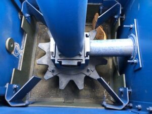
Flotation cell rotor speed optimization for mineral processing
✅ Rotor speed directly controls turbulence, air dispersion, and particle suspension in mechanical flotation cells
✅ Higher rotor speed can improve recovery up to a point, then causes particle detachment and froth instability
✅ The optimum rotor speed depends on cell design, rotor-stator geometry, particle size, and air rate
✅ Application 1: Fine-particle flotation benefits from higher shear and smaller bubbles
✅ Application 2: Coarse-particle flotation requires controlled turbulence to prevent detachment
| Item | Description |
|---|---|
| Function | Controls slurry circulation, turbulence, air dispersion, bubble size, particle suspension |
| Material | Rotor and stator components in wear-resistant alloys, rubber, or polyurethane |
| Application | Mechanical flotation cells in copper, gold, lead-zinc, nickel, and polymetallic plants |
| Service Life | Depends on abrasive slurry, rotor speed, and material selection |
| Benefits | Improved recovery, better bubble-particle collision, stable froth, controlled wear |
Rotor speed is one of the important operating variables in a mechanical flotation cell. It directly influences slurry circulation, turbulence, air dispersion, bubble formation, particle suspension, and bubble-particle collision.
However, increasing rotor speed does not always mean better flotation. In practice, flotation performance normally has an optimum operating range. A speed that is too low may provide insufficient mixing, while a speed that is too high can create excessive turbulence, particle detachment, froth instability, energy consumption, and equipment wear.
Understanding this relationship is important when operating or maintaining Flotation equipment.
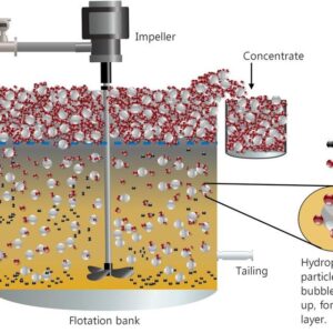
Mechanical flotation cell turbulence and particle suspension
The rotor transfers mechanical energy into the pulp. When rotor speed increases, slurry circulation and turbulence generally increase.
At a low rotor speed, the agitation may not be strong enough to keep all particles properly suspended. Some solids can settle in the cell, while air dispersion and particle movement may become less effective.
Increasing the speed can improve particle suspension and circulation. This can help bring mineral particles into contact with dispersed air bubbles.
However, excessive turbulence can become harmful. Strong turbulent flow may disturb the pulp-froth interface and can increase the possibility of particles detaching from bubbles.
Therefore, the objective is not simply to maximize turbulence, but to create sufficient turbulence for effective mixing and particle-bubble interaction without unnecessarily disturbing the froth.
Rotor speed also affects the way air is dispersed inside a mechanical flotation cell.
In many forced-air flotation systems, increasing impeller or rotor speed can increase shear and break larger bubbles into smaller bubbles. Smaller bubbles provide greater total surface area for a given amount of air, which can be useful for fine-particle flotation. Research on impeller-stator systems has found a relationship between impeller speed, bubble size, froth stability, and flotation performance.
However, the relationship is not identical for every flotation machine.
Cell design, rotor geometry, stator configuration, airflow rate, frother concentration, and aeration method can all change the resulting bubble size. For example, research on self-aerated machines has shown that the effect of rotor speed on bubble size can differ from forced-air systems.
This is why rotor speed should always be considered together with the complete Flotation Cells system rather than as an isolated number.
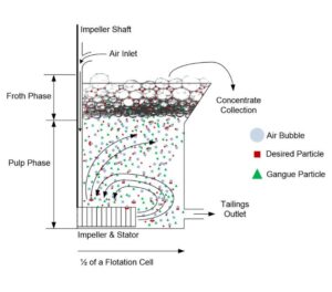
Rotor speed effect on bubble size in flotation
When the rotor speed is too low, particles may not remain properly suspended and air may not be dispersed effectively.
Increasing the speed can improve several conditions at the same time:
Better slurry circulation
Better particle suspension
More effective air dispersion
More bubble-particle collisions
Increased turbulence around the rotor-stator zone
Improved transport of attached particles toward the froth layer
These effects can be particularly important when treating fine particles because their flotation can be strongly influenced by collision and attachment conditions.
Laboratory research has found that flotation rate can increase with increasing energy dissipation until a maximum is reached, after which additional energy may provide little further benefit.
Industrial research also demonstrates why optimization should be based on actual plant conditions rather than a universal rpm value. In one industrial flash flotation study, changing rotor frequency from the normal operating condition to an optimized setting produced significant improvements in unit gold and copper recovery.
Yes.
Once the flotation cell reaches its effective operating range, further increasing rotor speed can have negative effects.
Excessive turbulence may cause already-attached mineral particles to detach from bubbles. It can also disturb the pulp-froth interface and increase water recovery or unwanted gangue entrainment.
The result can be a poorer balance between recovery and concentrate grade.
Excessive speed also increases mechanical energy consumption. Depending on the equipment design and operating conditions, higher mechanical loading can contribute to increased wear and maintenance requirements.
Therefore, the highest available rotor speed should not automatically be treated as the best operating condition.
Particle size is another important consideration.
Fine particles often require sufficient bubble surface area and effective collision conditions. Higher turbulence and suitable bubble dispersion can therefore help improve their flotation behavior.
Coarse particles can behave differently. If turbulence becomes excessive, particles that have already attached to bubbles may be more likely to detach.
This creates an important operating balance: the flotation cell needs enough energy to keep particles suspended and promote collision, but not so much energy that valuable particles are repeatedly detached from bubbles.
For this reason, the optimum rotor speed can depend on the particle-size distribution of the feed.
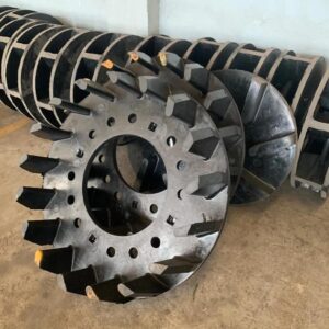
Flotation rotor and stator wear parts for mining plants
Rotor speed cannot be separated from rotor-stator design and condition.
The rotor generates the mechanical energy and circulation, while the stator influences the flow pattern and energy dissipation around the rotor.
Research has shown that impeller-stator design can affect bubble size, froth stability, and flotation performance.
Wear can also change the operating characteristics of flotation equipment over time. A worn rotor or stator may not produce the same flow and dispersion conditions as a new component.
For this reason, flotation equipment maintenance should consider both operating parameters and the physical condition of the Flotation Rotor & Stator Parts system. Plants that regularly inspect and replace worn components can maintain stable flotation kinetics and avoid unexpected downtime. For operators comparing replacement options, the guide on Rotor & Stator in Mechanical Flotation Cells explains how design and wear interact.
| Material | Wear Life | Cost | Best Application | Procurement Risk |
|---|---|---|---|---|
| Rubber | Moderate | Medium | Coarse particle flotation, low-impact zones | Low |
| Polyurethane | Long | Medium-High | Fine particle flotation, high-wear zones | Low |
| Wear-Resistant Alloy | Long | High | High-turbulence rotor-stator zones | Medium |
| Ceramic | Very Long | High | Severe abrasive slurry | Medium-High |
| Application | Recommended Rotor Speed | Key Risk | Recommended Component |
|---|---|---|---|
| Fine Particle Flotation | Higher range | Bubble coalescence | Polyurethane stator, high-shear rotor |
| Coarse Particle Flotation | Moderate range | Particle detachment | Rubber-lined rotor, reinforced stator |
| High-Density Pulp | Moderate-High | Excessive wear | Wear-resistant alloy rotor |
| Flash Flotation | Optimized frequency | Recovery loss | OEM-compatible rotor-stator set |
| Industry | Typical Ore | Flotation Challenge | Rotor Speed Consideration |
|---|---|---|---|
| Copper | Copper Ore | Fine liberation, high throughput | Higher shear for fine particles |
| Gold | Gold Ore | Flash flotation, coarse gold | Optimized frequency for recovery |
| Lead-Zinc | Lead Zinc Ore | Differential flotation | Controlled turbulence for selectivity |
| Nickel | Nickel Ore | Fine disseminated sulfides | High shear, small bubble dispersion |
| Polymetallic | Complex Sulfides | Multiple recovery stages | Stage-specific rotor speed settings |
When selecting rotor speed and rotor-stator components, consider:
Particle-size distribution — fine particles need higher shear; coarse particles need controlled turbulence
Cell design — forced-air and self-aerated cells respond differently to rotor speed
Rotor-stator geometry — design affects bubble size and energy dissipation
Air rate — interacts with rotor speed to determine bubble dispersion
Pulp density — higher density requires more energy for suspension
Frother concentration — affects froth stability and bubble size
Metallurgical target — recovery and concentrate grade balance
For a detailed comparison of wear materials used in flotation and screening circuits, see Polyurethane Screen vs Rubber Screen vs Wire Mesh: A Complete Comparison Guide. For buyers evaluating flotation wear parts specifically, the guide on Flotation Cell Rotor and Stator Wear Parts explains how component condition controls recovery and maintenance cost.
Flotation cell model and manufacturer
Rotor and stator part numbers (OEM or equivalent)
Rotor diameter and geometry
Stator configuration
Operating rotor speed range (rpm or frequency)
Pulp density and particle-size distribution
Air rate and frother type
Rotor assembly drawing
Stator assembly drawing
Wear zone dimensions
Mounting interface details
Provide OEM part numbers for cross-reference. A qualified supplier should be able to confirm interchangeability.
Rubber for coarse particle and low-impact zones
Polyurethane for fine particle and high-wear zones
Wear-resistant alloy for high-turbulence rotor-stator zones
Ceramic for severe abrasive slurry
MOQ: typically 1–5 sets depending on cell size
Lead time: 15–45 days depending on material and complexity
Packaging: export wooden case with rust protection
Shipping: sea freight for full sets, air freight for urgent spares
Dimensional check against drawings
Material certificate and hardness test
Dynamic balance check for rotor
Surface finish and defect inspection
Can the supplier manufacture according to drawings?
Can the supplier provide material reports?
Can the supplier support OEM replacement?
Does the supplier have export experience?
Can the supplier provide wear-life recommendations?
Can the supplier match the original rotor-stator geometry?
Can the supplier provide references from similar flotation plants?
Does the supplier offer trial quantities for evaluation?
Can the supplier provide installation guidance?
For operators sourcing flotation wear parts, the buyer guide on Which Manufacturer Offers High-Quality Polyurethane Tufflex Wire Screens for Mining? provides a useful supplier evaluation framework.
| Problem | Possible Cause | Recommended Solution |
|---|---|---|
| Premature rotor wear | Excessive rotor speed, abrasive slurry | Reduce speed, select wear-resistant alloy |
| Stator cracking | Fatigue, material mismatch | Verify material, check dynamic loading |
| Particle detachment | Excessive turbulence | Reduce rotor speed, adjust air rate |
| Froth instability | High shear, wrong frother | Adjust rotor speed, review reagent |
| Low recovery | Insufficient turbulence, poor dispersion | Increase speed within optimum range |
| High energy consumption | Rotor speed above optimum | Optimize frequency, check wear |
| Poor fitment | Incorrect dimensions, worn mounting | Verify drawings, replace mounting hardware |
| Material mismatch | Wrong material for application | Re-evaluate slurry abrasiveness |
| Installation failure | Incorrect torque, misalignment | Follow installation procedure |
Check rotor speed and power draw
Observe froth appearance and stability
Listen for unusual vibration or noise
Check air rate and dispersion
Inspect rotor-stator zone for visible wear
Verify pulp density and particle suspension
Measure rotor and stator wear
Check mounting bolts and alignment
Review recovery and grade trends
Document wear zones on rotor and stator
Compare wear rate against expected service life
Adjust rotor speed if wear accelerates
Replace rotor when wear exceeds allowable tolerance
Replace stator when flow pattern degrades
Replace both as a set when possible
Keep at least one rotor-stator set per cell size
Stock mounting hardware and seals
Maintain material certificates for traceability
Schedule replacement during planned shutdowns
Pre-assemble rotor-stator sets before shutdown
Train maintenance team on correct installation
Establish rotor speed optimization schedule
Monitor power consumption trend
Review wear data quarterly
Case Study
Customer Type: Copper concentrator, 5,000 tpd
Ore Type: Copper Ore with fine disseminated sulfides
Operating Conditions: Mechanical flotation cells, forced-air, rotor speed at maximum setting, high pulp density
Problem: Recovery plateaued despite maximum rotor speed. Concentrate grade declined. Rotor and stator wear accelerated, increasing maintenance cost.
Solution: Conducted step-by-step rotor speed optimization test. Reduced rotor frequency to optimized setting. Replaced worn rotor-stator set with polyurethane and wear-resistant alloy components matched to the application.
Result: Unit copper recovery improved by approximately 20%. Concentrate grade stabilized. Rotor-stator service life extended by approximately 30%. Energy consumption reduced.
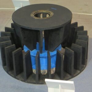
Flotation cell slurry circulation and air dispersion
Question: How does rotor speed affect flotation performance?
Answer: Rotor speed controls turbulence, air dispersion, bubble size, and particle suspension. Increasing speed improves recovery up to an optimum point, after which particle detachment, froth instability, and excess wear reduce performance. The optimum range depends on cell design, particle size, and operating conditions. Always optimize based on plant tests, not a universal rpm.
Question: What is the optimum rotor speed for a flotation cell?
Answer: There is no universal optimum. The best rotor speed depends on cell design, rotor-stator geometry, particle-size distribution, pulp density, air rate, and frother concentration. A controlled step-by-step test that monitors recovery, grade, froth stability, and power consumption is the most reliable way to find the optimum range for your plant.
Question: Can too much rotor speed reduce flotation recovery?
Answer: Yes. Excessive rotor speed creates strong turbulence that can detach already-attached particles from bubbles, disturb the pulp-froth interface, and increase gangue entrainment. It also raises energy consumption and accelerates rotor-stator wear. Recovery and concentrate grade can both decline when rotor speed exceeds the effective operating range.
Question: How does particle size affect optimum rotor speed?
Answer: Fine particles benefit from higher shear and smaller bubbles, which improve collision and attachment. Coarse particles are more likely to detach under excessive turbulence. This means the optimum rotor speed depends on the particle-size distribution of the feed and may need adjustment when feed conditions change.
Question: How does rotor-stator wear affect flotation performance?
Answer: A worn rotor or stator changes flow patterns, reduces air dispersion, and alters bubble size. This can reduce recovery and concentrate grade even if rotor speed remains unchanged. Regular inspection and timely replacement of Flotation Spares (Rotor & Stator) help maintain stable flotation performance.
Question: What materials are used for flotation rotor and stator parts?
Answer: Common materials include rubber, polyurethane, wear-resistant alloy, and ceramic. Rubber is suitable for coarse particle and low-impact zones. Polyurethane offers long wear life in fine-particle and high-wear zones. Wear-resistant alloy handles high-turbulence rotor-stator zones. Ceramic is used in severe abrasive slurry applications.
Question: How often should flotation rotor and stator be replaced?
Answer: Replacement timing depends on slurry abrasiveness, rotor speed, and material selection. Monitor wear patterns monthly and replace when wear exceeds allowable tolerance or when flow and dispersion degrade. Keeping one spare set per cell size helps reduce downtime. For related wear parts, see Flotation Impeller & Stator.
Question: Can rotor speed optimization reduce flotation operating cost?
Answer: Yes. Optimizing rotor speed can reduce energy consumption, slow rotor-stator wear, and improve recovery and grade balance. The goal is to find the speed that delivers the required metallurgical performance at the lowest reasonable energy and maintenance cost. This is usually not the highest available speed.
Question: How do I select a flotation rotor and stator supplier?
Answer: Evaluate the supplier on drawing compliance, material certification, OEM replacement capability, export experience, and wear-life recommendations. Request references from similar flotation plants and consider trial quantities. A supplier that understands your ore type and operating conditions can recommend the right material and geometry.
Question: What information do I need to request a flotation rotor and stator quote?
Answer: Provide the flotation cell model, OEM part numbers, rotor diameter and geometry, stator configuration, operating rotor speed range, pulp density, particle-size distribution, air rate, and frother type. Drawings and wear-zone dimensions help the supplier confirm fitment and material selection.
Rotor speed has a direct influence on the hydrodynamics of a mechanical flotation cell. Increasing speed can improve particle suspension, turbulence, air dispersion, and bubble-particle interaction, but excessive speed can create unwanted turbulence, particle detachment, froth instability, higher energy consumption, and increased wear.
The optimum condition therefore depends on the flotation cell design, rotor-stator system, particle size, pulp conditions, air rate, reagent conditions, and metallurgical target.
A controlled step-by-step test is usually a more reliable way to determine the appropriate operating range than selecting a rotor speed based only on rpm.
For mining plants, process optimization and equipment condition should also be considered together to maintain stable long-term operation. Plants that combine rotor speed optimization with timely replacement of Flotation Rotor & Stator Parts can achieve better recovery, lower energy cost, and longer maintenance intervals. For upstream and downstream process context, see Classification and Dewatering.
Related Products:
Related Technical Guides:
Rotor & Stator in Mechanical Flotation Cells: The Heart of Efficient Mineral Flotation
Flotation Cell Rotor and Stator Wear Parts: How They Control Recovery, Flow and Maintenance Cost
Hydrocyclone Wear: Root Causes, High-Wear Zones & Material Solutions
Related Buyer Guides:
Related Comparison Articles:
Polyurethane Screen vs Rubber Screen vs Wire Mesh: A Complete Comparison Guide
Self-Cleaning Screen vs Traditional Woven Wire Mesh: Which One Should You Choose?
Annie Lu
Email: annie.lu@huataogroup.com
Mobile: +86 18032422676 (WhatsApp / WeChat)
admin