Flotation Rotor vs Impeller: One Part, Two Air Strategies
-
 admin
- 22 Nov, 2026
Quick Answer
The rotor and the impeller are the same rotating component in most mechanical flotation cells: the bladed element on a vertical shaft that suspends solids, shears air into bubbles and drives circulation. The names differ by air supply. An impeller in a self-aspirating cell pulls its own air down a standpipe. A rotor in a forced-air cell receives blower air through a hollow shaft. Geometry and wear follow that split.
What Is a Flotation Rotor?
A flotation rotor is the rotating, bladed part at the bottom of a mechanical flotation cell. Mounted on a vertical shaft inside a stationary stator ring, it keeps solids in suspension, disperses air into fine bubbles and moves pulp through the tank so particles meet bubbles repeatedly. In induced-air machines the same part is usually called an impeller.
Key Takeaways
✔ Rotor and impeller name one component in most mechanical cells; the split is vocabulary plus air strategy.
✔ Induced-air impellers generate their own suction, so the eye and blade roots wear first and air draw falls early.
✔ Forced-air rotors take blower air, so tips and leading edges wear first and recovery drifts while power stays flat.
✔ Neither part works alone: clearance to the stator is a designed number and both parts wear toward opening it.
✔ Replace on measurement — roughly 15 to 20 percent mass loss, or doubled clearance — and replace as a matched pair.
Summary Table
| Item | Description |
| Function | Solids suspension, air dispersion into fine bubbles, pulp circulation and transfer |
| Material | Natural rubber, polyurethane, ceramic-reinforced composite, coated or lined steel |
| Application | Rougher, scavenger and cleaner duty across sulphide, gold, lithium and industrial mineral circuits |
| Service Life | Set by measured wear rate at the site, not by a calendar figure |
| Benefits | Stable recovery, predictable shutdowns, honest power draw, protection for downstream stages |
Definition: Rotor, Impeller and the Vocabulary Problem
Engineers inherit two vocabularies and usually keep both. “Impeller” comes from pump design: the vaned element that adds energy to a fluid, generating pressure and flow. “Rotor” comes from machine design: the rotating member of an assembly, defined by what it turns inside rather than by what it pumps.
Early self-aspirating flotation machines borrowed the pump word because their rotating part really did behave like a pump impeller. It lowered pressure at the blade roots, drew air down a standpipe and threw a slurry-air mixture outward. When large tank cells separated air supply from mixing duty, the part stopped pumping air altogether. “Rotor” described that better.
The industry never formally chose. Walk through the Flotation stage of any concentrator and you’ll hear both words inside one shift. Catalogues still list impellers for the XJK Flotation Cell and rotors for the XCF/KYF Flotation Cell, sometimes describing geometrically similar parts in different words. None of this is sloppiness. It’s just what happens when two engineering traditions share a component for a century.
For buyers, the useful conclusion is blunt: the name tells you which air strategy the supplier assumes. The dimensions tell you whether the part fits.
Working Principle: How Air Supply Shapes the Hardware
Start with the induced-air case, because it’s the older arrangement. The impeller spins, pressure drops at the blade roots, and atmospheric air travels down a standpipe into the eye of the part. Slurry and air meet in the blade passages, and the mixture leaves the periphery as a coarse, partly coalesced stream. The stator then redirects that stream and shears it again.
Because the impeller must generate suction and move slurry at the same time, its geometry compromises. The hub is open so air can enter. Blades are curved or conical so they can pump. Passage area is generous, because a narrow passage would choke air flow. Block the standpipe — rags, scale, a forgotten rag during maintenance — and the cell loses air and mixing together. Operators often read that as a mechanical failure.
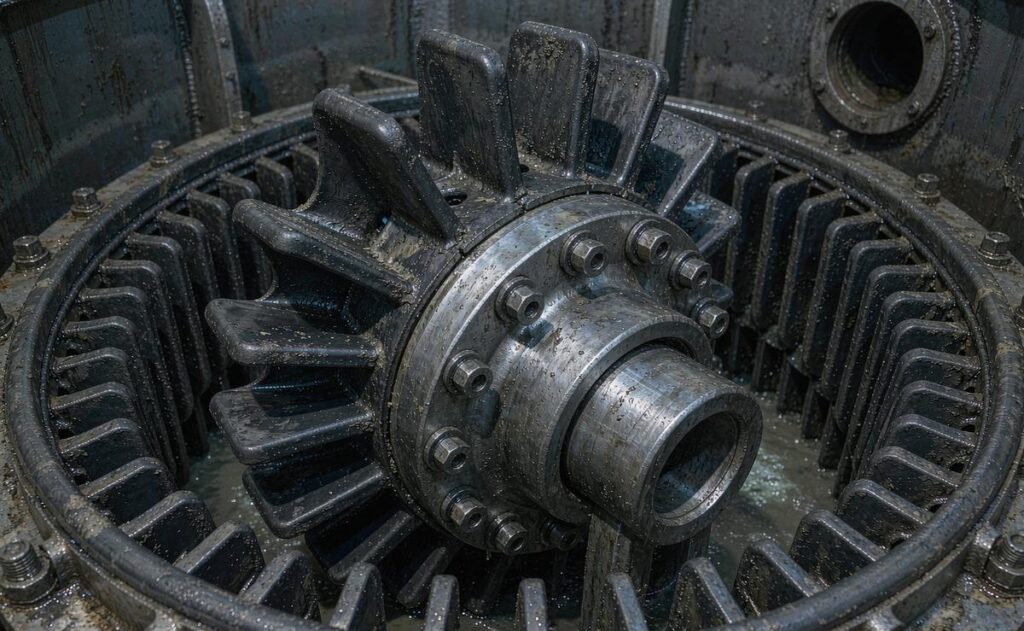
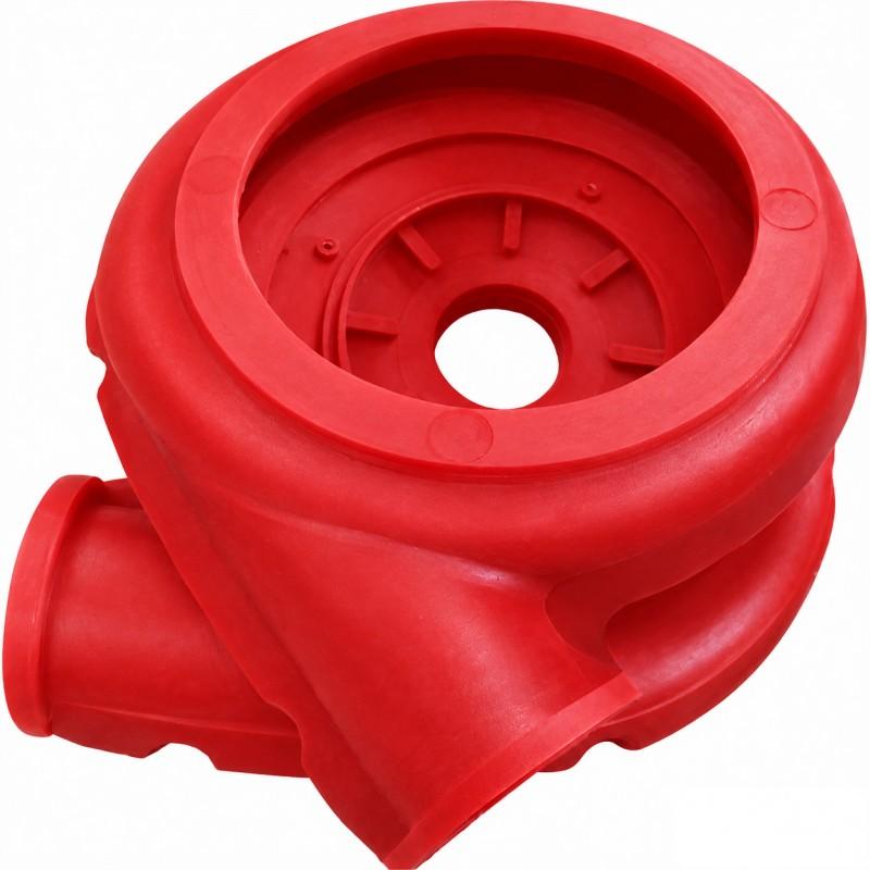
The rotating element inside its stator ring. Which air strategy it serves decides the blade profile.
Forced-air cells separate the two duties. A blower pushes air through a hollow shaft and a distributor that pre-spreads it across the blade passages. The rotor no longer needs suction, so geometry can be optimised for shear and circulation: closed hub, tighter clearance to the stator, more aggressive blade angles, higher tip speeds where the machine allows.
The consequence is control. Air volume becomes a panel setting rather than a by-product of speed and wear, and the Flotation Reagent Feeders upstream no longer have to compensate for a mechanism that can’t disperse what it’s given. That flexibility is why large tank cells dominate high-tonnage roughing, and why the Flotation Cells at modern concentrators are mostly forced-air designs.
It also changes how wear presents itself. A worn forced-air rotor keeps receiving its full air supply, so the blower pressure and flow look normal while bubble size coarsens. A worn induced-air impeller loses suction, so air draw falls and the froth goes flat. Same wear mechanism, different symptom, different instrument to trust.
Benefits
The first benefit is fit. Naming the air strategy correctly routes an enquiry to the right geometry — the split between the Flotation Impeller & Stator range and forced-air rotor parts exists for exactly this reason — and geometry is what makes a part work. A supplier who knows the cell is forced-air will quote a closed hub, a distributor interface and a blade profile designed for shear. One who assumes self-aspirating will quote an open eye and curved blades that won’t match the shaft.
The second is maintenance predictability. Both families wear gradually and measurably, which means replacement can be scheduled. Weigh the part at goods-in, weigh it at every pull, gauge the clearance to the stator, and photograph the blades. Three numbers and a photo turn a consumable into a forecast.
The third is process stability. Bubble size, suspension and circulation all depend on blade geometry. Hold the geometry inside specification and recovery holds with it. Let tips round off and the loss shows up as a slow drift nobody can attribute to chemistry — which is exactly when reagent consumption starts climbing for no reason.
The fourth is downstream protection. Cells that stop suspending solids sand out, and a sanded cell sends slugs of coarse material to the Thickeners, where the bill arrives as flocculant cost and water-balance trouble.
Applications
Rougher duty is the wear amplifier: coarse freshly ground pulp, high solids, maximum turbulence. Forced-air tank cells handle most large-tonnage copper and gold roughing, and their rotors are usually chosen for abrasion life at the tips.
Scavenger duty runs leaner pulp and lower froth depth. It tolerates simpler hardware and cheaper compounds, which is why smaller induced-air machines survive in that role.
Cleaner duty is gentler on impact and harsher on precision. Fine-particle recovery depends on bubble size, so a compound that rounds off quickly costs grade even though the part looks serviceable. Polyurethane usually earns its price here.
Industrial minerals, lithium whole-ore circuits and phosphate duty add chemistry to the list. A compound that survives abrasion may swell, harden or debond in a particular reagent regime, and no wear table predicts that. Trials do.
Feed preparation sits upstream of all of it. Drifting Hydrocyclones coarsen the overflow and shorten campaigns without anything changing at the cell; the Grinding circuit’s stability is part of the rotor’s service life, whether or not anyone writes it into the maintenance plan.
Material Comparison
| Property | Natural rubber | Polyurethane | Ceramic composite |
| Abrasion resistance | Moderate to good | Good to very good | Very high in high-velocity zones |
| Impact tolerance | High; deflects rather than cracks | Moderate; can crack under point impact | Low; bond integrity is the weak point |
| Chemical resistance | Compound-specific | Broad across pH ranges | Matrix-dependent |
| Profile retention | Lower; edges round earlier | High | High |
| Field repair | Patching possible | Limited | Not practical |
| Typical fit | Coarse roughing, corrosive pulp | Fine abrasive cleaner duty | Large tanks, high tip speed |
Application Comparison
| Duty | Priority | Starting point |
| Rougher, coarse feed | Abrasion life, impact tolerance | Composite or rubber |
| Scavenger, lean pulp | Cost per tonne | Rubber |
| Cleaner, fine values | Profile stability | Polyurethane |
| Small self-aspirating cell | Suction and simplicity | Rubber impeller |
| High-speed tank cell | Tip and edge life | Ceramic composite |
Treat the table as a starting point, not an answer. A plant with aggressive reagents may rule polyurethane out entirely, and an abrasive cleaner circuit may justify composite despite the price.
Industry Application Matrix
| Industry | Emphasis | First consideration |
| Copper | High-tonnage roughing, quartz abrasion | Compound selection against measured wear |
| Gold | Fine-bubble cleaning plus coarse roughing | Speed control and tramp protection |
| Lead-zinc | Many small cells, staged chemistry | Suction stability on induced-air units |
| Lithium | Whole-ore flotation, fine variable feed | Air flexibility and profile stability |
| Industrial minerals | Variable chemistry | Compatibility before wear resistance |
Selection Guide
Work in this order: machine, air path, duty, material, then commercial terms. Reversing it produces parts that look right and fit badly.
Machine first. Model, family and generation define the shaft connection, hub design and mounting pattern. A part for an SF Flotation Cell shares nothing with one for a forced-air tank cell, even when the diameters are close.
Air path second. Blower and hollow shaft means forced air. Standpipe and suction means induced air. If you can’t tell from the drawing, photograph the assembly with the cover off.
Duty third. Characterise the feed: ore type, particle size, solids concentration, pH, reagents, temperature, and the current campaign length. Vague answers produce vague material recommendations.
Material fourth. Match the dominant mechanism, not the sales literature. Abrasion, impact and chemistry are separate problems.
Commercial terms last, but early enough to matter: quantity, spare ratio, delivery window, inspection documents.
Procurement Guide
A complete enquiry is short and specific. Machine make, model and family. OEM part number if available. Drawings, or the worn sample, or photographs of both faces. Dimensions: outside diameter, overall height, bore diameter and taper, blade count, mounting hole pattern, rotational direction. Material preference or operating conditions. Quantity and spare ratio. Documents expected: dimensional report, as-new weight, hardness certificate, material report. Packaging suitable for sea freight.
Ask four questions of every supplier. Can you manufacture to drawings without the original part number? Can you supply material reports with the shipment? Can you support OEM replacement across machine generations? Can you give a wear-life expectation for our duty in writing?
Lead time depends mostly on pattern availability. Parts built on existing moulds ship in weeks; new patterns take longer. A supplier who explains the difference plainly is usually the one who holds the date, and the Flotation Rotor & Stator Parts range is organised around exactly this distinction between standard and bespoke geometry.
MOQ is rarely the constraint people fear. Most suppliers will build one part from a drawing, though the unit price reflects the setup. Ordering a matched set with a spare rotor is usually smarter than ordering three rotors and no stator.
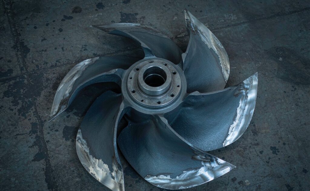
Concentrated damage is a diagnosis. Even wear is a schedule.
Failure Analysis
| Problem | Possible cause | Recommended solution |
| Premature blade wear | Coarse abrasive feed, soft compound | Re-check feed size, review material grade |
| Cracks at blade root | Tramp metal impact, brittle compound | Screen upstream, move to rubber |
| Loss of air draw | Blocked standpipe, worn impeller eye | Clear the air path, replace the impeller |
| Recovery drift, stable power | Opened rotor-stator clearance | Gauge clearance, replace as a pair |
| Vibration at speed | Imbalance, loose hub, bent shaft | Inspect assembly, torque and align |
| Poor fit on installation | Wrong family or generation | Verify drawing against the machine |
| One-sided wear | Misalignment or biased feed entry | Align the mechanism, check the feed box |
| Rapid wear after material change | Chemistry or duty mismatch | Trial again with compatibility data |
Maintenance Guide
Daily: listen at the platform, check for vibration, confirm air pressure on forced-air cells and suction behaviour on self-aspirating ones.
Weekly: log power draw and blower pressure, inspect the standpipe mouth, and note froth depth across the bank. A single cell behaving differently from its neighbours is the earliest useful signal.
Monthly: review trends rather than snapshots. Recovery drifting with stable power points at clearance; power rising with stable recovery points at something else entirely.
Every shutdown: gauge rotor-to-stator clearance, weigh the part, photograph the blades, record hours. Replace at roughly 15 to 20 percent mass loss or doubled clearance, and inspect the stator at the same time — the pair wears together whether or not anyone plans for it.
Spares: hold one matched set per critical cell. The Flotation Spares (Rotor & Stator) range exists because plants learned this the hard way. Track consumption by cell number; rotors in one bank never wear at the same rate, and knowing which one leads the pack is worth more than an average.
Case Study
Customer type: copper concentrator with a six-cell forced-air rougher bank.
Ore type: sulphide copper in quartz gangue, primary grind near 120 microns.
Operating conditions: high solids, warm pulp, continuous duty, moderate reagent dose.
Problem: recovery drifted lower across two campaigns while power draw stayed flat and no reagent change helped. A shutdown inspection found rotor tips heavily worn and the rotor-to-stator clearance roughly doubled. The stators had not been changed with the previous rotor set.
Solution: fitted matched rotor and stator sets, recorded clearance at installation, moved to a compound better suited to the abrasive feed, and started weighing parts at every pull.
Result: recovery returned to its earlier band within one campaign, and the following replacement was scheduled from measured wear instead of a calendar. Nothing dramatic. Just predictable.
FAQ
Is an impeller the same as a rotor in a flotation cell?
In most mechanical cells, yes. Both words name the single rotating bladed part at the bottom of the tank. The practical difference is air supply: induced-air machines tend to say impeller, forced-air tank cells say rotor. Describe the air path and supply dimensions when ordering, rather than relying on the label alone.
Why do catalogues list impellers and rotors as separate products?
Because the geometry differs. An induced-air impeller has an open hub, a suction eye and curved blades sized to pull air down a standpipe. A forced-air rotor has a closed hub, a distributor interface and blade angles tuned for shear. The two are not interchangeable even when diameters match.
Can I fit an impeller into a forced-air cell?
Not as a like-for-like swap. The shaft connection, hub design and air path differ, and the blade geometry assumes suction the machine doesn’t provide. Retrofit kits exist for some machines, but they come engineered, with a new distributor and a documented performance basis.
How do I identify which design my cell uses?
Follow the air. A blower and duct feeding the cell, or a hollow shaft, means forced air. An open standpipe above the pulp that the mechanism draws from means self-aspirating. The machine model confirms it, and the OEM manual settles any argument. Photograph the assembly before removal.
Which material suits abrasive copper feed?
Polyurethane or a ceramic composite usually outlast natural rubber on sharp, high-tonnage feed, provided tramp metal is controlled. Rubber remains the better choice where impact risk is real or where reagents attack the polymer. Trial one cell and measure before converting a bank.
How often should rotor and stator be replaced?
On measurement, not on time. Gauge clearance at every shutdown and weigh the parts against their as-new records. Replace the pair at roughly 15 to 20 percent mass loss, or when clearance has about doubled. Coarse sharp feed moves those thresholds earlier; fine cleaner duty can extend them.
Does a worn rotor always show in power draw?
No. On forced-air cells the blower supplies air regardless of clearance, so a worn rotor can draw normal power while doing less useful work. Recovery trend, froth texture and bubble size are earlier indicators. Power draw still matters on induced-air machines, where suction depends on blade condition.
What should I send with a replacement enquiry?
Machine make, model and family, plus the OEM part number if you have it. Drawings, the worn sample, or clear photographs of both faces. Five dimensions: diameter, height, bore and taper, blade count, mounting pattern. Material preference, quantity, delivery window and inspection requirements.
Can a supplier manufacture without the OEM part number?
Yes, from drawings, photographs and measured dimensions, or from the worn sample. The part number speeds up identification but isn’t essential. What is essential is the machine family, because it defines the air path, hub design and mounting interface the replacement must match.
How do I stop repeat failures in the same cell?
Look for the cause outside the part. Misalignment, a biased feed entry, tramp metal from upstream screening, or a standpipe that keeps choking will reproduce the same failure on a new rotor. Fix the cause first, then fit the part.
Conclusion
Rotor or impeller — the argument matters less than what the words imply about air. One rotating part, two engineering traditions, two air strategies. Once you know which strategy your cells use, the geometry, the wear pattern and the replacement procedure all become obvious.
Buy on dimensions and documentation, describe the air path in one sentence, and measure at every shutdown. Replace the pair together, keep the two families apart in the store, and let the wear record set the schedule. That is the whole discipline, and it costs a scale, a gauge and a notebook.
Related Articles
Related Products
- Flotation Cells
- Flotation Impeller & Stator
- XJK Flotation Cell
- SF Flotation Cell
- XCF/KYF Flotation Cell
Related Technical Guides
- Rotor & Stator in Mechanical Flotation Cells
- Flotation Cell Rotor and Stator Wear Parts
- Hydrocyclone Wear: Root Causes, High-Wear Zones and Material Solutions
- Hydrocyclone Underflow Too Wet? 6 Causes and Fixes
- Improve Fine Screening Efficiency with Polyurethane Screen Panels
Related Buyer Guides
- How Do I Choose the Right Rubber Belt for a Vacuum Belt Filter?
- Which Manufacturer Offers High-Quality Polyurethane Tufflex Wire Screens for Mining?
Related Comparison Articles
- Polyurethane Screen vs Rubber Screen vs Wire Mesh: A Complete Comparison Guide
- Self-Cleaning Screen vs Traditional Woven Wire Mesh
Contact
Lassie Lu
Email: sale40@huataogroup.com
WhatsApp / WeChat: +86 18033766300
Website: www.tufflexscreen.com
HTL Solutions manufactures flotation rotors, impellers and matched stators in rubber, polyurethane and ceramic composite, built to OEM drawings or from worn samples, with dimensional reports, as-new weights and hardness certificates on every shipment.
 admin
personal profile