How Often Should I Replace Hydrocyclone Liners?
Oct 20, 2026
 admin
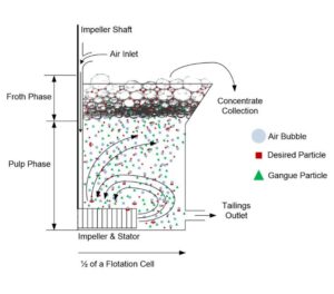
The flotation rotor generates energy, circulation, and air dispersion, while the stator controls and redirects flow to reduce excessive swirling. Together they create the hydrodynamic environment required for bubble-particle attachment, froth stability, and consistent mineral recovery.
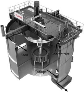
Flotation cell rotor and stator mechanism showing slurry circulation and air bubble dispersion.
Rotor = energy, circulation, suspension, air dispersion
Stator = flow control, swirl reduction, circulation distribution
Worn geometry changes flow, turbulence, and bubble-particle contact
Recovery loss can occur before obvious mechanical failure
Coarse and high-density particles are most sensitive to poor suspension
Selection must consider the complete rotor-stator system, not one component
Wear-resistant materials extend service life and maintain flotation performance
Proper clearance and installation directly affect hydrodynamic efficiency
| Item | Description |
|---|---|
| Function | Rotor creates energy; stator controls flow |
| Material | Rubber, polyurethane, high-chrome alloy, ceramic, composite |
| Application | Mechanical flotation cells in mineral processing |
| Key Parameters | Air dispersion, slurry pumping, turbulence, flow distribution |
| Wear Factors | Abrasiveness, particle size, slurry density, operating speed |
| Replacement Trigger | Geometry change, recovery loss, power increase |
In a mechanical flotation cell, the rotor and stator are the core components controlling slurry movement, air dispersion, particle suspension, and bubble-particle interaction. The rotor, also called an impeller, is the rotating component positioned near the bottom of the cell. The stator is the stationary component surrounding or positioned close to the rotor.
The rotor transfers mechanical energy into the slurry and generates circulation and turbulence. The stator controls and redirects the high-velocity flow leaving the rotor. Together they form a matched hydrodynamic system whose performance directly influences flotation recovery.
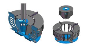
Different flotation rotor and stator designs for controlling slurry flow and air dispersion.
The basic flotation mechanism can be understood through a simple sequence:
Slurry + air → Rotor mixing → Rotor-stator turbulence → Bubble dispersion → Particle-bubble collision → Attachment → Bubble rise → Froth recovery
Every stage depends on appropriate hydrodynamics.
The rotor draws slurry through the stator and expels it to the sides, creating a suction that draws air down the shaft of the stator. The air is then dispersed as bubbles through the slurry and comes in contact with particles in the slurry that is drawn through the stator.
If the rotor does not generate sufficient circulation, coarse particles may settle. If air is not properly dispersed, the available bubble surface area and bubble distribution may become less effective. If the stator does not properly control the rotor discharge, excessive swirling or uneven circulation may develop.
If turbulence is too weak, particle-bubble collisions may be insufficient. If turbulence is too strong, attached particles may be more vulnerable to detachment.
This means the best flotation performance does not necessarily come from simply increasing rotor speed. The objective is to establish a balanced combination of suspension, air dispersion, circulation, turbulence, and froth stability.
ALT: Simplified flotation cell diagram showing rotor, stator, slurry circulation, air bubbles, and particle-bubble contact.
A properly designed and maintained rotor-stator system provides:
Improved slurry suspension, especially for coarse and high-density particles
More consistent air dispersion and bubble distribution
Better bubble-particle contact and attachment
Reduced excessive swirling and unproductive vortexing
More stable froth conditions
Lower power consumption per unit of flotation performance
Longer component service life with wear-resistant materials
Reduced maintenance downtime and replacement frequency
More consistent metallurgical performance
Flotation rotor and stator systems are used across multiple mineral processing applications:
Copper ore flotation – bulk sulphide and selective flotation
Gold ore flotation – free gold and sulphide-associated gold
Lead-zinc ore flotation – selective separation of galena and sphalerite
Nickel ore flotation – bulk and selective nickel flotation
Phosphate ore flotation – anionic and cationic flotation
Rare earth ore flotation – complex flowsheet applications
Coal flotation – fine coal recovery
Iron ore flotation – reverse flotation of silica
Lithium ore flotation – spodumene and associated minerals
In the selection of FLOTATION SPARES (ROTOR & STATOR), different ore types place different demands on rotor pumping capacity and stator flow control. Selection must be based on specific operating conditions.
Flotation cell rotor assembly during inspection showing wear condition and maintenance.
| Material | Wear Life | Cost | Maintenance | Best Application |
|---|---|---|---|---|
| Rubber | Moderate | Low | Easy | Fine particles, low abrasion |
| Polyurethane | High | Medium | Easy | Abrasive slurry, medium particles |
| High-chrome alloy | Very high | High | Moderate | Coarse, dense particles |
| Ceramic | Very high | High | Difficult | Severe abrasion, fine particles |
| Composite | High | Medium-High | Moderate | Mixed duty conditions |
| Application | Rotor Requirement | Stator Requirement | Critical Factor |
|---|---|---|---|
| Coarse particles | High pumping capacity | Strong flow control | Suspension |
| Fine particles | Moderate pumping | Uniform dispersion | Bubble-particle contact |
| High-density slurry | High power | High wear resistance | Power draw |
| Abrasive ore | High wear resistance | High wear resistance | Service life |
| High air rate | Efficient dispersion | Uniform distribution | Bubble surface area |
| Viscous slurry | Strong circulation | Effective flow control | Flow pattern |
| Industry | Typical Flotation Duty | Rotor-Stator Priority | Recommended Material |
|---|---|---|---|
| Copper | Bulk sulphide flotation | Wear resistance | High-chrome alloy |
| Gold | Free gold and sulphide | Circulation | Polyurethane |
| Lead-Zinc | Selective flotation | Flow control | Rubber or polyurethane |
| Nickel | Bulk and selective | Turbulence balance | High-chrome alloy |
| Phosphate | Anionic flotation | Air dispersion | Polyurethane |
| Rare Earth | Complex flowsheet | Consistency | Composite |
| Coal | Fine coal recovery | Circulation | Rubber |
| Iron Ore | Reverse flotation | Wear resistance | High-chrome alloy |
| Lithium | Spodumene flotation | Flow control | Polyurethane |
The replacement rotor and stator should match the flotation cell and existing mechanism. Important information may include:
Flotation machine model
Cell volume
Rotor diameter
Stator diameter
Shaft arrangement
Installation dimensions
Rotation direction
Existing rotor/stator design
The required balance between suspension, mixing, and turbulence depends partly on the feed material. A circuit treating relatively coarse, dense particles may require different pumping and suspension characteristics from a circuit treating fine particles.
Important process information can include:
Solids concentration
Particle size distribution
Mineral density
Slurry abrasiveness
Slurry viscosity
Feed throughput
Air rate
Operating temperature and chemical environment
These factors influence the wear rate and hydrodynamic requirements of the rotor-stator assembly.
The clearance between the rotor and stator is another important design parameter. Changing the gap can influence local velocity, turbulence, energy dissipation, and circulation. For this reason, the clearance should be considered as part of the complete mechanism rather than as an isolated dimension.
In mineral processing applications, component durability is particularly important because the slurry may contain highly abrasive particles. A suitable wear-resistant design can help maintain the intended geometry for longer, reducing the frequency of replacement and helping keep flotation performance more consistent.
The practical replacement process should also be considered. Correct dimensions, reliable installation, appropriate materials, and consistent manufacturing quality can help reduce maintenance downtime.
Between CLASSIFICATION and flotation, the hydrodynamic matching of the rotor-stator system also affects overall circuit stability.
| Parameter | Why It Matters |
|---|---|
| Air dispersion | Determines how effectively air is distributed through the pulp |
| Slurry pumping | Helps keep particles suspended and circulate pulp |
| Turbulence | Influences bubble-particle collision and attachment |
| Flow distribution | Helps avoid excessive swirl and poorly mixed zones |
| Rotor-stator clearance | Affects local velocity and energy dissipation |
| Power consumption | Indicates the energy required for the desired hydrodynamic performance |
| Wear resistance | Determines how well the geometry can be maintained during operation |
| Service life | Influences maintenance frequency and operating cost |
| Compatibility | Ensures the assembly matches the existing flotation mechanism |
Research using experimental measurements and computational fluid dynamics has shown that different rotor geometries can produce different flow fields, turbulence distributions, circulation volumes, and power requirements. Therefore, when comparing designs, it is useful to look at the complete relationship:
Rotor geometry + stator geometry + clearance + rotation speed + air rate + slurry properties
rather than evaluating one component independently.
ALT: Different flotation rotor and stator designs for controlling slurry flow and air dispersion.
Flotation machine manufacturer and model
Cell volume
Rotor diameter
Stator diameter
Shaft arrangement
Installation dimensions
Rotation direction
Existing rotor/stator design
Rotor drawing
Stator drawing
Assembly drawing
Installation drawing
Provide OEM part numbers if available to ensure compatibility.
Rubber
Polyurethane
High-chrome alloy
Ceramic
Composite
Confirm with supplier based on order quantity and production planning.
Confirm with supplier. Lead time depends on material, quantity, and customization requirements.
Export-standard packaging to protect components during transport.
Sea, air, or express depending on order size and urgency.
Dimensional check
Material certificate
Surface finish
Hardness test
Assembly check
Can the supplier manufacture according to drawings?
Can the supplier provide material reports?
Can the supplier support OEM replacement?
Does the supplier have export experience?
Can the supplier provide wear-life recommendations?
For FLOTATION IMPELLER & STATOR procurement, priority should be given to confirming the supplier’s ability to manufacture according to drawings and provide material traceability.
| Problem | Possible Cause | Recommended Solution |
|---|---|---|
| Premature wear | Abrasive slurry, wrong material | Upgrade material, review slurry characteristics |
| Cracking | Fatigue, impact, thermal stress | Review design and installation, improve material toughness |
| Blinding | Fine particles, incorrect clearance | Adjust clearance, review particle size distribution |
| Pegging | Coarse particles, low pumping | Increase pumping capacity, review rotor design |
| Low efficiency | Worn geometry, incorrect clearance | Replace rotor and stator, confirm dimensions |
| Excessive downtime | Poor planning, no spare parts | Improve spare parts inventory, plan replacement windows |
| Poor fitment | Incorrect dimensions, wrong part number | Confirm drawings and OEM part numbers |
| Material mismatch | Wrong material for application | Review slurry abrasiveness and operating conditions |
| Installation failure | Incorrect procedure, damaged during installation | Follow OEM procedure, inspect before installation |
| Increased power draw | Worn rotor, excessive turbulence | Replace worn components, review operating speed |
Check vibration and noise
Check power draw
Check air rate and dispersion
Check froth behavior
Check wear pattern on rotor and stator
Check rotor-stator clearance
Check bolts and fasteners
Check seals and connections
Check alignment
Check shaft condition
Check bearing condition
Record wear measurements
Record wear measurements regularly
Trend wear rate over time
Identify high-wear zones
Adjust maintenance schedule based on trend
Replace based on wear trend, not fixed interval
Replace when geometry change affects flotation performance
Replace rotor and stator as a matched pair when possible
Keep critical spares on site
Maintain minimum stock levels
Review inventory based on consumption rate
Plan replacement during scheduled shutdowns
Prepare tools and documentation in advance
Train maintenance team on correct procedure
Schedule regular inspections
Monitor operating parameters
Address small issues before they become major failures
Maintain records for trend analysis
In the grinding and classification stages, the stability of GRINDING MILLS and HYDROCYCLONES also affects flotation feed conditions and should be included in the overall maintenance strategy.
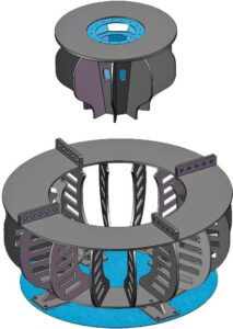
Wear-resistant flotation rotor and stator components for slurry mixing and air dispersion.
Customer Type: Copper concentrator
Ore Type: Copper sulphide
Operating Conditions: Abrasive slurry, coarse particles, high throughput
Problem: Reduced flotation recovery, increased power draw, unstable froth conditions
Solution: Replaced worn rotor and stator with wear-resistant high-chrome alloy design. Confirmed correct clearance and installation. Reviewed operating speed and air rate.
Result: Restored slurry circulation, improved air dispersion, stabilized froth conditions, and improved recovery consistency. Reduced unplanned downtime.
Q1: What is the function of the rotor and stator in a flotation cell?
A: The rotor generates energy, circulation, and air dispersion. The stator controls and redirects flow, reducing excessive swirling. Together they create the hydrodynamic environment required for bubble-particle attachment and stable flotation recovery.
Q2: How does wear affect flotation recovery?
A: Wear changes rotor and stator geometry, which changes flow patterns, turbulence, and bubble-particle contact. This can reduce recovery before obvious mechanical failure. Monitor wear patterns and process performance together.
Q3: How do I select the right rotor and stator?
A: Consider flotation cell model, particle size, slurry characteristics, rotor-stator clearance, wear resistance, and maintenance requirements. Review the complete system, not one component.
Q4: What materials are used for rotor and stator?
A: Common materials include rubber, polyurethane, high-chrome alloy, ceramic, and composite. Selection depends on slurry abrasiveness, particle size, and operating conditions.
Q5: How often should rotor and stator be replaced?
A: Replacement timing depends on wear rate, slurry abrasiveness, and operating conditions. Monitor wear patterns and trend data to plan replacement. Avoid fixed-interval replacement without condition monitoring.
Q6: Can I replace only the rotor or only the stator?
A: In most cases, rotor and stator should be evaluated as a matched pair. Replacing only one component may not restore the original hydrodynamic performance. Review clearance and flow pattern.
Q7: What information do I need to provide for a replacement?
A: Provide flotation machine manufacturer and model, cell volume, drawings, dimensions, rotation speed, slurry characteristics, and current wear problems. Photos of existing components are also helpful.
Q8: How can I reduce flotation rotor and stator wear?
A: Select the right material, maintain correct clearance, monitor wear patterns, and follow preventive maintenance. Avoid excessive turbulence and ensure proper installation.
Q9: What is the difference between self-aspirated and forced-air flotation cells?
A: In self-aspirated cells, the rotor draws air into the pulp. In forced-air cells, air is supplied externally and mixed by the rotor. Rotor and stator design requirements differ between the two types.
Q10: How does rotor-stator clearance affect flotation performance?
A: Clearance affects local velocity, turbulence, energy dissipation, and circulation. Incorrect clearance can reduce air dispersion, increase power draw, and reduce flotation efficiency.
In the dewatering stage after flotation, the stable operation of THICKENERS and FILTER PRESSES also depends on stable upstream flotation conditions.
The rotor and stator are much more than simple mechanical components inside a flotation cell. Together, they create and control the hydrodynamic environment required for effective flotation.
The rotor provides energy, circulation, suspension, and air dispersion, while the stator controls the resulting flow and reduces excessive swirling. Their geometry, clearance, operating speed, and wear condition can influence bubble distribution, particle suspension, bubble-particle collision, and ultimately flotation performance.
For this reason, rotor and stator selection should consider the complete flotation process, including ore characteristics, particle size, slurry properties, air rate, cell design, operating conditions, and wear requirements.
A properly matched and well-maintained rotor-stator system can help maintain stable flotation conditions and support consistent mineral-processing performance.
For flotation rotor and stator selection support, contact HUATAO Group.
Related Products
Related Technical Guides
FLOTATION CELL ROTOR AND STATOR WEAR PARTS: HOW THEY CONTROL RECOVERY, FLOW AND MAINTENANCE COST
ROTOR & STATOR IN MECHANICAL FLOTATION CELLS: THE HEART OF EFFICIENT MINERAL FLOTATION
HYDROCYCLONE WEAR: ROOT CAUSES, HIGH-WEAR ZONES & MATERIAL SOLUTIONS
IMPROVE FINE SCREENING EFFICIENCY WITH POLYURETHANE SCREEN PANELS
Related Buyer Guides
WHICH MANUFACTURER OFFERS HIGH-QUALITY POLYURETHANE TUFFLEX WIRE SCREENS FOR MINING?
HOW DO I CHOOSE THE RIGHT RUBBER BELT FOR A VACUUM BELT FILTER?
POLYURETHANE SCREEN VS RUBBER SCREEN VS WIRE MESH: A COMPLETE COMPARISON GUIDE
Related Comparison Articles
Annie Lu
Email: annie.lu@huataogroup.com
Mobile: +86 18032422676
WhatsApp / WeChat
admin