How Often Should I Replace Hydrocyclone Liners?
Oct 20, 2026
 admin
A flotation impeller affects bubble size mainly through the turbulence and circulation it generates inside the pulp. Higher impeller speed increases bubble breakup and reduces mean bubble size under fixed air-flow conditions, while higher air flow tends to increase mean bubble size. Impeller geometry, stator design, frother concentration and slurry properties also shape the final gas-dispersion behaviour.
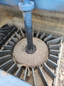
Higher impeller speed increases turbulence and bubble breakup, producing smaller bubbles — with diminishing returns and rising energy cost.
Increasing air flow rate at fixed RPM generally increases mean bubble size.
Impeller diameter, blade geometry, tip speed and stator design shift bubble distribution even at identical RPM.
The impeller and stator work as one system; stator design can reduce Sauter mean bubble diameter and improve froth stability.
Impeller wear changes flow geometry over time, degrading circulation, air dispersion and flotation consistency.
| Item | Description |
|---|---|
| Function | Mix slurry, disperse air, maintain solids suspension, generate bubble breakup |
| Material | Rubber, polyurethane, composite elastomer, wear-resistant alloy |
| Application | Mechanical flotation cells in copper, gold, lead-zinc, nickel, phosphate and coal circuits |
| Key Variables | Impeller speed, air flow rate, impeller geometry, stator design, frother concentration |
| Reported Bubble Range | Approximately 284 μm to 727 μm in controlled laboratory tests |
| Wear Mode | Abrasive erosion, chemical attack, cavitation at blade tips |
| Replacement Trigger | Geometry loss, reduced air dispersion, falling recovery, rising power draw |
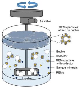
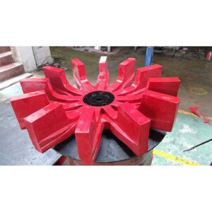
A flotation impeller is the rotating component inside a mechanical flotation cell that draws in and disperses air into mineral slurry. It generates the turbulent flow field required to break air into bubbles and to keep solid particles suspended. Working together with a stationary stator, the impeller defines the hydrodynamic environment in which bubble-particle attachment occurs. In mineral processing circuits, the impeller is part of the broader FLOTATION stage, and is normally supplied as a matched rotor-stator set within FLOTATION CELLS.
The impeller rotates inside the flotation cell, creating a low-pressure zone near the shaft that draws air down into the pulp. As the air meets the rotating blades, the turbulent shear field deforms and breaks large bubbles into smaller ones. Simultaneously, bubbles collide and coalesce — so the final bubble-size distribution reflects a dynamic balance between breakup and coalescence.
Smaller bubbles provide greater gas-liquid interfacial area for particle attachment, which generally supports recovery. However, extremely fine bubbles can reduce buoyancy and slow flotation kinetics. The stator surrounds the impeller and redirects the radial flow, converting rotational energy into a controlled circulation pattern that distributes bubbles throughout the pulp volume rather than concentrating them near the impeller.
Industrial-scale research has shown that mean bubble size decreases as impeller speed increases, while increasing air flow rate increases mean bubble size. A laboratory example reported a median bubble diameter reduction from approximately 727 μm to 284 μm when impeller speed increased from 700 to 1,200 rpm under controlled aeration and frother conditions.
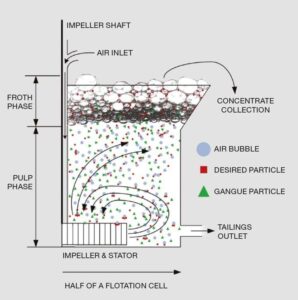
The basic function of a flotation impeller is to create circulation and turbulence inside the pulp.
Air enters the flotation cell and interacts with the rotating impeller. The turbulent flow generated around the impeller can deform and break larger bubbles into smaller ones. At the same time, bubbles can also collide and merge, a process known as coalescence.
Therefore, the final bubble size represents a balance between bubble breakup and bubble coalescence.
Smaller bubbles generally provide a greater gas-liquid interfacial area for particle attachment. However, producing the smallest possible bubbles is not necessarily the only objective because flotation performance also depends on air distribution, particle suspension and froth stability.
At a fixed air flow rate, increasing impeller speed generally increases turbulence and bubble breakup.
This means that higher impeller speed can produce smaller bubbles under suitable operating conditions. However, the relationship has practical limits. Once sufficient turbulence has been created, additional speed may provide only a limited reduction in bubble size while increasing energy consumption and turbulence.
The effect can also change in self-aerated flotation machines. In these systems, increasing impeller speed may increase the amount of air drawn into the cell. The additional air can change the final bubble-size distribution, so the simple rule of “higher speed equals smaller bubbles” should not be applied universally.
A laboratory example reported a reduction in median bubble diameter from approximately 727 μm to 284 μm when impeller speed increased from 700 to 1,200 rpm under controlled aeration and frother conditions.
This demonstrates the effect of increased breakup under those specific conditions rather than establishing a universal operating target. Plants that track wear life against hydraulic performance will find the analysis in FLOTATION CELL ROTOR AND STATOR WEAR PARTS: HOW THEY CONTROL RECOVERY, FLOW AND MAINTENANCE COST a practical reference point.
RPM alone cannot fully describe the performance of a flotation impeller.
Impeller diameter, blade geometry, position and tip speed all influence the circulation and turbulent flow generated inside the cell. Different impeller designs can therefore produce different bubble distributions even when operated at similar speeds.
The location of the bubbles also matters. Bubbles may be relatively large near the air-entry or shaft region, experience stronger breakup around the impeller, and then change again as they travel through the pulp.
This means that measuring bubble size at only one point may not accurately represent the entire flotation cell.
The impeller and stator should be considered as a combined system.
The impeller creates rotational flow and turbulence, while the stator modifies and guides the resulting flow pattern. This interaction can improve air dispersion and influence the size distribution of bubbles throughout the pulp. A detailed treatment of why the pairing matters more than either part alone is given in ROTOR & STATOR IN MECHANICAL FLOTATION CELLS: THE HEART OF EFFICIENT MINERAL FLOTATION.
Research comparing impeller-stator configurations has shown that stator design can reduce the Sauter mean bubble diameter and improve froth stability under tested conditions.
However, a flotation cell does not need the maximum possible turbulence. Excessive turbulence reaching the pulp-froth interface can disturb the lower froth and negatively affect flotation performance.
Therefore, the practical objective is to find a suitable combination of:
Impeller speed
Air flow rate
Impeller geometry
Stator design
Frother concentration
Slurry conditions
Solids suspension
Froth stability
Rather than optimizing one parameter independently, operators should evaluate the complete gas-dispersion system.
Improved bubble-particle attachment: Smaller, well-dispersed bubbles increase collision probability with hydrophobic particles.
Stable froth: Correct stator design limits excessive turbulence at the pulp-froth interface.
Consistent solids suspension: Proper impeller geometry prevents sanding and dead zones.
Lower energy cost: Matching impeller speed to duty avoids over-turbulence and wasted power.
Longer wear life: Correct material selection extends rotor and stator service intervals.
Predictable maintenance: Geometry-controlled wear allows planned replacement rather than reactive shutdowns.
Flotation impellers and stators are used across a wide range of mineral processing duties:
Copper ore flotation: Rougher, scavenger and cleaner cells where air dispersion directly affects recovery.
Gold ore flotation: Sulphide-associated gold circuits requiring stable bubble generation.
Lead-zinc ore flotation: Differential flotation where selective bubble-particle attachment is critical.
Nickel ore flotation: Fine-grained sulphide circuits sensitive to bubble size distribution.
Phosphate flotation: Large-volume cells where solids suspension must be maintained across the tank.
Coal flotation: Fine coal circuits where froth stability and bubble size influence clean coal yield.
The impeller does not operate in isolation. Feed preparation through GRINDING and CLASSIFICATION determines the particle size distribution reaching flotation, while downstream DEWATERING and FILTRATION handle the concentrates and tailings produced.
| Material | Wear Resistance | Chemical Resistance | Typical Application | Relative Cost |
|---|---|---|---|---|
| Natural Rubber | Good | Moderate | Coarse-particle flotation, low-acid circuits | Low |
| Polyurethane | Very Good | Good | Fine-particle flotation, abrasive slurry | Medium |
| Wear-Resistant Alloy | Excellent | Variable | High-impact zones, coarse feed | High |
| Composite Elastomer | Very Good | Very Good | Aggressive chemical environments | Medium-High |
| Ceramic-Lined | Excellent | Excellent | Extreme wear points | High |
Rubber rotor and stator parts perform well in coarse, low-acidity pulps where impact resistance matters more than fine-particle wear. Polyurethane offers better resistance to fine abrasive slurry and holds dimensional accuracy longer, which matters when flow geometry must remain stable between replacements. Alloy and ceramic options are usually reserved for the highest-wear zones where elastomer life is unacceptable.
| Application | Dominant Wear Mechanism | Recommended Material | Replacement Interval Driver |
|---|---|---|---|
| Copper Rougher | Abrasive erosion | Polyurethane | Air dispersion loss |
| Copper Cleaner | Abrasive + chemical | Polyurethane / Composite | Froth stability decline |
| Gold Sulphide | Abrasive erosion | Rubber / Polyurethane | Recovery drop |
| Lead-Zinc Differential | Chemical + abrasive | Composite Elastomer | Selectivity loss |
| Nickel Fine Sulphide | Fine abrasive | Polyurethane | Bubble size drift |
| Phosphate Large Cell | Abrasive + scale | Polyurethane | Circulation loss |
| Coal Fine Circuit | Mild abrasive | Rubber | Froth quality decline |
| Industry | Typical Cell Type | Impeller Duty | Key Concern |
|---|---|---|---|
| Copper | Mechanical, large volume | High air dispersion | Recovery and grade balance |
| Gold | Mechanical, medium volume | Stable bubble generation | Sulphide flotation kinetics |
| Lead-Zinc | Mechanical, multi-stage | Selective dispersion | Differential selectivity |
| Nickel | Mechanical, fine feed | Fine bubble generation | Slime coating and entrainment |
| Phosphate | Mechanical, large volume | Bulk circulation | Solids suspension |
| Coal | Mechanical, fine circuit | Froth-stable dispersion | Clean coal yield |
| Rare Earth | Mechanical, specialised | Controlled turbulence | Reagent-sensitive circuits |
Before specifying a flotation impeller or stator, confirm the following parameters:
Flotation machine model and manufacturer
Impeller/rotor diameter and blade configuration
Stator dimensions and slot geometry
Operating RPM range
Motor power and drive arrangement
Design air flow rate
Slurry density and solids concentration
Mineral characteristics, including particle size and abrasiveness
Existing rotor and stator material
Current wear condition and remaining service life
These parameters determine whether a replacement component can maintain the required mixing and air-dispersion characteristics. A properly matched impeller-stator system should generate suitable bubbles while maintaining solids suspension and stable circulation — without introducing unnecessary turbulence at the froth interface.
Where flotation feed is prepared by cyclones, matching the HYDROCYCLONES and SPIRAL CLASSIFIERS to the same duty helps keep feed conditions stable, which in turn makes impeller performance more predictable.
Required Information
Flotation machine model and serial number
Rotor diameter, blade count and blade angle
Stator dimensions, slot count and mounting pattern
Operating RPM and motor power
Air flow rate and blower specification
Slurry density, pH and temperature range
Mineral type and particle size distribution
Drawings Needed
Dimensional drawing of existing rotor and stator
Mounting bolt pattern and shaft interface detail
Blade profile cross-section
Stator slot arrangement
OEM Part Numbers
Where OEM part numbers are available, they should be cross-referenced against the replacement supplier’s catalogue. Where they are not, dimensional drawings become the primary specification.
Material Selection
Material choice must reflect the dominant wear mechanism — abrasive erosion, chemical attack or cavitation. Polyurethane is commonly selected for fine abrasive slurry, rubber for coarse impact-dominated duties, and composite elastomers where chemical exposure is significant.
MOQ, Lead Time, Packaging and Shipping
Minimum order quantities vary by material and mould availability. Elastomer rotor and stator parts typically require mould preparation time. Packaging must protect blade edges from deformation during transit; sea freight is standard for bulk orders, with air freight reserved for urgent replacements.
Inspection Standards
Incoming inspection should verify dimensional accuracy against drawings, material hardness, surface finish and freedom from mould defects such as voids or flash.
Supplier Evaluation Checklist
Can the supplier manufacture according to drawings?
Can the supplier provide material reports?
Can the supplier support OEM replacement?
Does the supplier have export experience?
Can the supplier provide wear-life recommendations?
For plants comparing replacement sources, the considerations set out in FLOTATION CELL ROTOR AND STATOR WEAR PARTS: HOW THEY CONTROL RECOVERY, FLOW AND MAINTENANCE COST are directly relevant to supplier selection.
| Problem | Possible Cause | Recommended Solution |
|---|---|---|
| Premature wear | Material mismatch with slurry abrasiveness | Switch to polyurethane or composite elastomer |
| Blade cracking | Impact from coarse particles or tramp metal | Install trommel or magnetic protection upstream |
| Loss of air dispersion | Worn blade geometry reducing shear | Replace rotor and inspect stator simultaneously |
| Excessive power draw | Over-speed or excessive pulp density | Reduce RPM or adjust slurry density |
| Poor froth stability | Excessive turbulence reaching froth interface | Review stator design and impeller speed |
| Uneven wear pattern | Misalignment or shaft runout | Check shaft alignment and bearing condition |
| Bolt loosening | Vibration and inadequate torque | Re-torque to specification and use locking devices |
| Cavitation damage | Air entry restriction or low pulp level | Verify air supply and cell level control |
| Reduced recovery | Bubble size drift from worn geometry | Measure bubble size and replace worn parts |
| Short stator life | Slot geometry causing localized turbulence | Review stator slot design with supplier |
Daily Inspection
Check motor current draw against baseline
Listen for unusual vibration or noise from the drive
Verify air flow rate at the control valve
Observe froth appearance and bubble texture
Weekly Inspection
Inspect rotor and stator through access hatch where possible
Check bolt torque on rotor mounting
Verify pulp level control is functioning correctly
Monthly Inspection
Measure wear on rotor blade tips and stator slots
Compare measured wear against expected wear curve
Check shaft alignment and bearing condition
Wear Pattern Monitoring
Photograph rotor and stator at each inspection to build a wear history. Uneven wear patterns indicate alignment or flow distribution problems that should be corrected before replacement.
Replacement Timing
Replace rotor and stator as a matched set where possible. Replacing only one component against a worn partner often produces poor flow matching and accelerated wear on the new part.
Spare Parts Inventory
Hold at least one complete rotor-stator set per critical cell, plus mounting hardware. For multi-cell circuits, a shared spare set can reduce capital tied up in inventory.
Downtime Reduction
Schedule replacement during planned shutdowns. Pre-assemble mounting hardware and prepare lifting equipment in advance to minimise cell downtime.
Preventive Maintenance
Track power draw, recovery and bubble appearance as leading indicators. A gradual rise in power draw with falling recovery often signals impeller wear before visible damage appears.
Customer Type: Mid-sized copper concentrator, 8,000 tpd
Ore Type: Sulphide copper ore with moderate pyrite content
Operating Conditions: Rougher flotation cells, 1,000 rpm impeller speed, slurry density 35% solids, pH 10.5
Problem: Gradual recovery decline over four months, accompanied by rising motor current draw and visibly coarser froth. Inspection revealed significant blade tip wear on the rotors and slot erosion on the stators.
Solution: Replaced rotor and stator as matched polyurethane sets across the rougher bank. Verified impeller speed and air flow rate against design values, and confirmed shaft alignment before restart.
Result: Recovery returned to baseline levels within two weeks of replacement. Motor current draw fell back to the original design range. The plant adopted a matched-set replacement policy and added blade tip measurement to the monthly inspection routine.
Question: How does impeller speed affect bubble size in a flotation cell?
Answer: Higher impeller speed increases turbulence, which increases bubble breakup and generally reduces mean bubble size under fixed air-flow conditions. However, the benefit diminishes once sufficient turbulence exists, and additional speed mainly increases energy consumption. In self-aerated cells, higher speed also draws in more air, which can offset the bubble-size reduction.
Question: Does increasing air flow make bubbles larger or smaller?
Answer: Increasing air flow rate at a fixed impeller speed generally increases mean bubble size, because more air is introduced than the impeller can effectively disperse. The practical approach is to balance air flow rate against impeller speed so that the impeller can disperse the air volume without excessive coalescence.
Question: What is the difference between the impeller and the stator?
Answer: The impeller rotates and generates the turbulent flow that disperses air into bubbles. The stator is stationary and surrounds the impeller, redirecting the flow to create a controlled circulation pattern. Working together, they determine the bubble-size distribution and the overall hydrodynamic environment in the cell.
Question: How do I know when to replace a flotation rotor or stator?
Answer: Key indicators include rising motor current draw, declining recovery, coarser froth texture, and visible blade tip or slot wear. Measuring blade geometry at monthly inspections and comparing against the original dimensions gives a more reliable trigger than waiting for visible damage.
Question: Can I replace only the rotor without replacing the stator?
Answer: Replacing only one component against a worn partner usually produces poor flow matching, which can accelerate wear on the new part. Where budget allows, replacing rotor and stator as a matched set gives more predictable hydraulic performance and longer combined service life.
Question: What material is best for flotation impellers?
Answer: Material choice depends on the dominant wear mechanism. Polyurethane performs well in fine abrasive slurry and holds dimensional accuracy longer. Rubber is preferred where coarse-particle impact dominates. Composite elastomers suit chemically aggressive pulps. The correct choice requires matching material to slurry conditions rather than applying a single default.
Question: Can a replacement impeller match OEM performance?
Answer: A replacement impeller can match OEM performance when it is manufactured to the same dimensions, blade geometry and material specification. Dimensional drawings and material reports are essential. Buyers should confirm that the supplier can manufacture to drawing and provide verification of material properties before ordering.
Question: How does impeller wear affect flotation recovery?
Answer: As rotor and stator surfaces wear, the original flow geometry changes. This reduces shear at the blade tips, weakening air dispersion and shifting the bubble-size distribution. Circulation and solids suspension also degrade. The combined effect is a gradual decline in recovery that often becomes visible only after several months of operation.
A flotation impeller affects bubble size mainly through the turbulence and circulation it generates. Higher impeller speed increases bubble breakup and reduces bubble size under controlled air-flow conditions, while higher air flow increases bubble size. However, impeller speed is only one part of the system.
Impeller geometry, stator design, air flow, frother concentration and slurry properties all influence the final gas-dispersion behaviour. Flotation performance should therefore be evaluated using bubble size, air distribution, solids suspension and froth stability together, rather than focusing on bubble size alone.
Plants that treat flotation as one stage of a complete flowsheet — from CRUSHING and GRINDING through CLASSIFICATION and flotation to DEWATERING and TAILING management — generally achieve more consistent recovery than those optimising a single unit in isolation.
Related Products
Related Technical Guides
FLOTATION CELL ROTOR AND STATOR WEAR PARTS: HOW THEY CONTROL RECOVERY, FLOW AND MAINTENANCE COST
ROTOR & STATOR IN MECHANICAL FLOTATION CELLS: THE HEART OF EFFICIENT MINERAL FLOTATION
HYDROCYCLONE WEAR: ROOT CAUSES, HIGH-WEAR ZONES & MATERIAL SOLUTIONS
IMPROVE FINE SCREENING EFFICIENCY WITH POLYURETHANE SCREEN PANELS
Related Buyer Guides
WHICH MANUFACTURER OFFERS HIGH-QUALITY POLYURETHANE TUFFLEX WIRE SCREENS FOR MINING?
HOW DO I CHOOSE THE RIGHT RUBBER BELT FOR A VACUUM BELT FILTER?
Related Comparison Articles
POLYURETHANE SCREEN VS RUBBER SCREEN VS WIRE MESH: A COMPLETE COMPARISON GUIDE
SELF-CLEANING SCREEN VS TRADITIONAL WOVEN WIRE MESH: WHICH ONE SHOULD YOU CHOOSE?
Annie Lu
Email: annie.lu@huataogroup.com
Mobile / WhatsApp / WeChat: +86 18032422676
admin