How Often Should I Replace Hydrocyclone Liners?
Oct 20, 2026
 admin
What is rotor-stator clearance in a flotation cell?
Rotor-stator clearance is the gap between the rotating rotor and the stationary stator in a mechanical flotation cell. It controls slurry circulation, turbulence intensity, air dispersion and bubble-particle attachment stability. The optimum gap depends on mechanism design, operating conditions, particle size and component wear — not on a universal “smaller is better” rule.
A narrower rotor-stator gap increases local shear and turbulence, which can improve bubble breakup and air dispersion.
Excessive turbulence from a gap that is too small can detach mineral particles already attached to bubbles, reducing recovery.
A gap that is too large weakens mixing and air dispersion, causing poor bubble-particle contact and possible solids settling.
Fine and coarse particles respond differently to clearance changes; recovery should be evaluated by particle-size fraction, not overall recovery alone.
Rotor and stator wear changes the hydraulic behavior of the whole mechanism and should be assessed together.
| Item | Description |
|---|---|
| Function | Controls slurry circulation, air dispersion and turbulence in mechanical flotation cells |
| Material | Elastomer, polyurethane, rubber or wear-resistant metal, depending on duty |
| Application | Copper, lead-zinc, gold, nickel, phosphate and other sulfide and oxide flotation circuits |
| Critical Dimension | Gap between rotor periphery and stator surface, specified by the equipment manufacturer |
| Key Wear Zones | Rotor blade tips, stator inner surfaces, air passages, protective linings |
| Replacement Trigger | Manufacturer wear limits, measured clearance change, drop in aeration uniformity or recovery by size fraction |
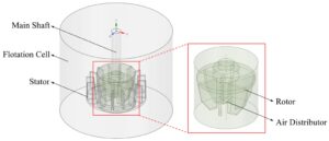
Rotor-stator clearance is the physical gap between the rotating rotor (or impeller) and the stationary stator inside a mechanical flotation cell. The rotor generates the pumping action and shear that disperses air into the slurry. The stator stabilizes the flow pattern and directs the dispersed air-slurry mixture into the separation zone.
This gap is not a single fixed number. It is a design parameter that depends on rotor diameter, blade geometry, stator configuration, rotational speed, cell volume, and the specific duty of the flotation circuit.
In the broader mineral processing flow, flotation sits after CLASSIFICATION and before DEWATERING. The performance of the flotation mechanism depends on the particle size distribution delivered by upstream classification, and it directly affects the downstream dewatering and filtration duty.
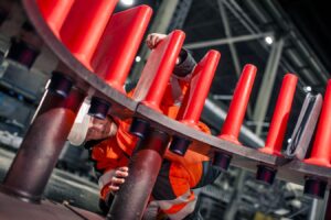
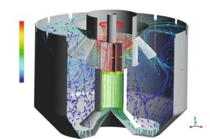
The rotor rotates at a controlled speed and creates a pressure differential that draws slurry and air into the mechanism. As the slurry-air mixture passes through the rotor-stator region, velocity gradients and turbulence break larger bubbles into smaller ones.
Smaller bubbles provide more interfacial area for particle collection, provided air dispersion is uniform and other operating conditions support attachment.
The stator converts some of the rotational energy into a more stable flow pattern. This helps distribute the aerated slurry into the cell volume and keeps mineral particles in suspension.
Clearance directly affects this process. A narrow gap increases local velocity gradients, turbulent energy dissipation and shear stress. A wide gap reduces these effects and can weaken mixing.
Upstream classification performance also matters. If HYDROCYCLONES are not delivering a consistent particle size distribution, the flotation mechanism has to compensate for wider feed variability, which makes clearance evaluation and optimization more difficult.
Stable air dispersion and consistent bubble size distribution
Effective slurry circulation that keeps coarse particles suspended
Predictable bubble-particle attachment and reduced detachment losses
Lower specific power consumption per tonne of ore treated
Longer service life of rotor and stator components through controlled wear
More stable metallurgical performance across the flotation bank
Correct rotor-stator clearance matters across a wide range of mineral processing duties:
Copper sulfide flotation — where coarse liberated particles require strong suspension without excessive detachment
Lead-zinc differential flotation — where stable air dispersion supports selective separation
Gold flotation — where fine gold and gold-bearing sulfides require uniform bubble-particle contact
Nickel and PGM flotation — where fine disseminated values need consistent mixing
Phosphate and potash flotation — where reagent-froth interactions are sensitive to turbulence intensity
Coal flotation — where fine coal recovery depends on stable bubble-particle attachment
Tailings retreatment circuits — where variable feed characteristics make clearance stability more important
Flotation cells used in these duties are covered under the broader FLOTATION process category, and equipment selection should always match the specific ore and duty.
| Material | Wear Life | Cost | Maintenance | Best Application |
|---|---|---|---|---|
| Natural Rubber | Moderate | Low | Easy | Coarse particle duties with moderate abrasion |
| Polyurethane | Long | Medium | Easy | Fine particle duties, high abrasion, moderate impact |
| Wear-Resistant Elastomer | Long | Medium-High | Moderate | Mixed duty with impact and abrasion |
| High-Chrome Alloy | Very Long | High | Difficult | High-impact, coarse-particle primary duties |
| Ceramic-Reinforced Composite | Very Long | High | Moderate | Severe abrasion, limited impact |
Material selection should match the actual wear mechanism — abrasion, impact, corrosion or a combination — rather than relying on hardness alone.
| Duty Condition | Recommended Clearance Approach | Reason |
|---|---|---|
| Coarse particle flotation | Moderate gap, strong circulation | Maintains suspension without excessive detachment |
| Fine particle flotation | Standard gap, uniform air dispersion | Supports bubble-particle collision frequency |
| High-density slurry | Verify manufacturer specification | Prevents mechanical interference and excessive power draw |
| Variable feed size | Review clearance during feed changes | Prevents performance drift when feed varies |
| Abrasive ore | Check clearance during wear inspections | Wear changes effective gap over time |
| Industry | Ore Type | Typical Flotation Duty | Clearance Consideration |
|---|---|---|---|
| Copper | Copper sulfide | Rougher, scavenger, cleaner | Balance coarse suspension and detachment risk |
| Lead-Zinc | Sulfide ore | Differential flotation | Stable air dispersion for selectivity |
| Gold | Free gold and sulfide | Rougher, cleaner | Uniform bubble-particle contact |
| Nickel | Nickel sulfide | Rougher, cleaner | Fine disseminated values need consistent mixing |
| Phosphate | Sedimentary phosphate | Rougher, cleaner | Reagent-froth sensitivity to turbulence |
| Coal | Fine coal | Froth flotation | Stable attachment for fine coal recovery |
| Tailings | Retreatment feed | Scavenger | Variable feed requires stable mechanism |
Selecting the correct rotor-stator configuration involves several engineering steps:
Identify the flotation cell model and mechanism type. Different cell designs (XJK, SF, XCF/KYF and others) use different rotor-stator geometries. The clearance specification is mechanism-specific.
Confirm the original equipment dimensions. Rotor diameter, blade profile, stator configuration and mounting interface must match the cell.
Review the duty conditions. Ore type, particle size distribution, slurry density, pH and reagent regime all influence the appropriate clearance and material selection.
Assess the wear mechanism. Abrasion, impact, corrosion or a combination determines material selection.
Verify manufacturer specifications. The clearance should match the original equipment design unless a controlled trial justifies a change.
Plan for inspection access. Clearance measurement and wear inspection require safe access to the mechanism during maintenance windows.
For plants operating XCF/KYF or similar cells, reviewing the XCF/KYF FLOTATION CELL specification helps confirm the correct mechanism configuration before ordering replacement components.
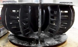
A structured procurement process reduces the risk of incorrect fitment and premature failure.
Required Information
Flotation cell make, model and mechanism type
Original equipment part numbers where available
Rotor diameter, blade profile and stator configuration
Material specification and hardness requirements
Operating conditions: ore type, slurry density, pH, temperature
Expected service life and replacement interval
Drawings Needed
Assembly drawing of the rotor-stator mechanism
Dimensional drawing with clearance specification
Material specification sheet
Installation interface drawing
OEM Part Numbers
Where OEM part numbers are available, they should be provided to the supplier for cross-reference. Where they are not available, dimensional drawings and photographs are essential.
Material Selection
Material selection should match the actual wear mechanism. Polyurethane is often suitable for fine-particle duties with moderate impact. Rubber performs well in coarse-particle duties with moderate abrasion. Wear-resistant elastomers and composites are used where combined abrasion and impact occur.
MOQ, Lead Time, Packaging, Shipping
Typical MOQ for custom rotor and stator components depends on the mechanism size and material. Lead time varies with material availability and manufacturing complexity. Components should be packaged to prevent distortion during transport, and shipping method should match the required delivery schedule.
Inspection Standards
Incoming inspection should verify:
Dimensional accuracy against drawings
Material certification and hardness
Surface finish and absence of defects
Fitment against the mounting interface
Supplier Evaluation Checklist
Can the supplier manufacture according to drawings?
Can the supplier provide material reports?
Can the supplier support OEM replacement?
Does the supplier have export experience?
Can the supplier provide wear-life recommendations?
Buyers comparing suppliers can review how manufacturers document their FLOTATION ROTOR & STATOR PARTS specification, material data and inspection standards. This level of documentation is a practical indicator of engineering support capability.
| Problem | Possible Cause | Recommended Solution |
|---|---|---|
| Premature wear | Material mismatch, incorrect clearance, abrasive slurry | Review material selection and verify clearance against specification |
| Cracking | Impact loading, thermal stress, casting defects | Inspect for foreign objects, review material toughness |
| Blinding (air passages) | Blocked air or slurry passages, scale buildup | Clean passages, review air supply quality |
| Pegging (solids accumulation) | Weak circulation, oversized particles, low rotor speed | Review clearance, rotor speed and feed size distribution |
| Low efficiency | Worn rotor or stator, incorrect clearance, poor air dispersion | Measure clearance, inspect wear profile, compare recovery by size fraction |
| Excessive downtime | Frequent unplanned replacement, poor fitment | Improve inspection schedule and verify dimensional accuracy |
| Poor fitment | Incorrect dimensions, wrong part number, drawing mismatch | Verify drawings and part numbers before ordering |
| Material mismatch | Selection based on hardness alone | Match material to actual wear mechanism |
| Installation failure | Incorrect torque, misalignment, damaged sealing surfaces | Follow installation procedure and verify alignment |
Daily Inspection
Check operating power draw and aeration uniformity
Listen for abnormal noise or vibration from the mechanism
Monitor froth appearance and recovery trends
Weekly Inspection
Review recovery by particle-size fraction
Check for changes in air dispersion
Inspect for visible wear or damage where accessible
Monthly Inspection
Measure clearance where accessible
Inspect rotor blade profiles and stator surfaces
Check protective linings for wear or exposure of metal substrate
Wear Pattern Monitoring
Record wear profile at fixed inspection points
Compare against previous inspections to track wear rate
Identify uneven wear that may indicate misalignment or incorrect clearance
Replacement Timing
Follow the equipment manufacturer’s wear limits
Replace when measured clearance exceeds specification
Replace when recovery by size fraction declines without other explanation
Spare Parts Inventory
Maintain at least one set of rotor and stator components for critical cells
Store components to prevent distortion and material degradation
Verify incoming parts against drawings before installation
Downtime Reduction
Plan replacement during scheduled shutdowns
Pre-assemble and verify fitment before the shutdown window
Coordinate with upstream and downstream process teams
Preventive Maintenance
Follow a documented inspection schedule
Track wear rate to predict replacement intervals
Review operating conditions after any feed or reagent change
Customer Type: Copper concentrator, mid-sized operation
Ore Type: Copper sulfide with moderate pyrite content
Operating Conditions: Mechanical flotation cells in rougher and scavenger duty, slurry density approximately 30–35% solids, pH 10–11, abrasive gangue with quartz
Problem: Recovery in the scavenger bank declined gradually over several months. Operators initially suspected a change in feed mineralogy. Power draw in the affected cells was lower than usual, which was initially interpreted as improved efficiency.
Solution: Mechanical inspection showed measurable rotor wear and stator surface wear. The effective clearance had increased beyond the manufacturer’s specification. The rotor blade tips had worn unevenly, reducing pumping capacity and air dispersion. Replacement rotor and stator components were installed with dimensions verified against drawings. Clearance was set to the manufacturer’s specification.
Result: Power draw returned to normal operating range. Recovery by particle-size fraction improved in the scavenger bank, particularly in the intermediate size range. No change was made to reagent dosage or air rate, which confirmed the improvement was related to the mechanism condition rather than other operating variables.
Question: How much does a flotation rotor and stator cost?
Answer: Cost depends on cell size, mechanism type, material and quantity. Standard elastomer or polyurethane components are typically less expensive than high-chrome or composite alternatives. Buyers should compare total cost of ownership — including wear life, downtime and replacement frequency — rather than unit price alone. Requesting a quotation with material specification and wear-life estimate provides a more accurate basis for comparison.
Question: What material is best for flotation rotor and stator components?
Answer: There is no single best material. Polyurethane performs well in fine-particle duties with moderate impact. Rubber is suitable for coarse-particle duties with moderate abrasion. Wear-resistant elastomers and composites are used where combined abrasion and impact occur. Material selection should match the actual wear mechanism, not rely on hardness alone. Providing operating conditions and wear history to the supplier supports accurate selection.
Question: How do I know if the rotor-stator clearance is correct?
Answer: Start with the equipment manufacturer’s specification. Verify clearance during maintenance inspections using the recommended measurement method. If clearance has increased beyond specification due to wear, replacement is typically required. Any intentional adjustment should be based on controlled plant trials with consistent operating conditions and recovery measured by particle-size fraction.
Question: What is the typical service life of a flotation rotor and stator?
Answer: Service life varies widely with ore abrasiveness, slurry density, rotor speed, air rate and material selection. In abrasive duties, components may require replacement within months; in milder duties, service life may extend considerably longer. Tracking wear rate at fixed inspection points provides a more reliable basis for planning than a generic service-life figure.
Question: Can I replace only the rotor, or should I replace the rotor and stator together?
Answer: Rotor and stator should generally be assessed together. Wear on either component changes the hydraulic behavior of the complete mechanism. Replacing only one component may leave the mechanism operating outside its design condition. In most cases, replacing both as a matched set maintains the intended clearance and flow pattern.
Question: Are aftermarket rotor and stator parts compatible with OEM equipment?
Answer: Compatibility depends on dimensional accuracy, material specification and fitment. A qualified aftermarket supplier should manufacture according to drawings or verified dimensions and provide material reports. Buyers should confirm the supplier’s ability to support OEM replacement before ordering. FLOTATION SPARES (ROTOR & STATOR) components from a documented supplier reduce the risk of fitment issues.
Question: How does rotor-stator wear affect flotation recovery?
Answer: As the rotor wears, its pumping capacity and air dispersion capability decline. Stator wear changes flow resistance and turbulence characteristics. The combined effect can reduce bubble-particle attachment efficiency and cause solids settling. Recovery by particle-size fraction is a useful indicator of mechanism condition, particularly when other operating variables are stable.
Question: How often should rotor and stator components be inspected?
Answer: Inspection frequency depends on duty severity. In abrasive or high-tonnage duties, monthly inspection is common. In milder duties, quarterly inspection may be sufficient. Daily monitoring of power draw and aeration uniformity provides early warning of mechanism deterioration between scheduled inspections.
Question: Does a lower power draw always mean better flotation efficiency?
Answer: No. Lower power draw may indicate reduced pumping capacity caused by worn components, rather than improved efficiency. This is a common misinterpretation in flotation circuits. Power draw should be interpreted together with aeration uniformity, slurry circulation, and recovery by particle-size fraction.
Question: Can rotor-stator clearance be adjusted on site?
Answer: Some mechanisms allow limited clearance adjustment, but the range is defined by the equipment design. Adjustments beyond the manufacturer’s specification risk mechanical interference, excessive power draw or damage to components. Any adjustment should be based on equipment requirements and controlled trials, not on a general assumption that a narrower gap is better.
Rotor-stator clearance affects flotation recovery through its influence on turbulence, air dispersion, slurry circulation and bubble-particle interactions. A gap that is too large weakens mixing; a gap that is too small can create excessive shear and increase the risk of particle detachment.
The practical approach is to follow the equipment manufacturer’s clearance specification, inspect the rotor and stator together for wear, and evaluate any change using consistent operating conditions and recovery by particle-size fraction. Combined with application-appropriate wear parts and a documented maintenance schedule, this supports stable flotation performance over the service interval.
Related Products
Related Technical Guides
FLOTATION CELL ROTOR AND STATOR WEAR PARTS: HOW THEY CONTROL RECOVERY, FLOW AND MAINTENANCE COST
ROTOR & STATOR IN MECHANICAL FLOTATION CELLS: THE HEART OF EFFICIENT MINERAL FLOTATION
HYDROCYCLONE WEAR: ROOT CAUSES, HIGH-WEAR ZONES & MATERIAL SOLUTIONS
IMPROVE FINE SCREENING EFFICIENCY WITH POLYURETHANE SCREEN PANELS
Related Buyer Guides
WHICH MANUFACTURER OFFERS HIGH-QUALITY POLYURETHANE TUFFLEX WIRE SCREENS FOR MINING?
HOW DO I CHOOSE THE RIGHT RUBBER BELT FOR A VACUUM BELT FILTER?
Related Comparison Articles
POLYURETHANE SCREEN VS RUBBER SCREEN VS WIRE MESH: A COMPLETE COMPARISON GUIDE
SELF-CLEANING SCREEN VS TRADITIONAL WOVEN WIRE MESH: WHICH ONE SHOULD YOU CHOOSE?
Annie Lu
Email: annie.lu@huataogroup.com
Mobile: +86 18032422676
WhatsApp / WeChat
admin