Flotation Rotor Function: What It Does and How to Manage It
-
 admin
- 18 Nov, 2026
Quick Answer
The rotor in a flotation machine is the rotating impeller at the tank bottom performing three simultaneous functions: suspending slurry so particles stay in circulation, shearing injected air into the fine bubbles that carry minerals into the froth, and driving the mixing that disperses reagents and moves pulp through the circuit. Recovery depends on all three, and all three decay together on the rotor’s wear curve.
What Is a Flotation Rotor?
A flotation rotor is the rotating submerged component of a mechanical flotation machine, mounted on a vertical shaft and running close to a stationary stator ring. The rotor creates the contact opportunities between particles and bubbles that make froth flotation possible; everything else in the machine supports that one job. Those Flotation Cells come in many sizes, but every one of them is organized around the same spinning component.
Key Takeaways
✔ The rotor suspends slurry, shears air into fine bubbles, and drives mixing and inter-cell transfer.
✔ Wear degrades all three functions together — and the loss shows up as slow recovery drift.
✔ Power draw and rotor weight are the cheapest early-warning instruments in the plant.
✔ Replace at roughly 15–20% mass loss or doubled rotor-stator clearance.
✔ Rubber, polyurethane, and ceramic composite each own a distinct duty in the circuit.
Summary Table
| Item | Description |
| Function | Slurry suspension, air shearing, reagent dispersion, inter-cell transfer |
| Material | Natural rubber, polyurethane, ceramic-reinforced composite |
| Application | Rougher, cleaner, scavenger rotors across sulphide flotation machines |
| Service Life | Months per campaign; decided by measured weight loss and clearance |
| Benefits | Stable recovery, planned shutdowns, power efficiency, protected downstream equipment |
Definition
The rotor sits at the bottom of a mechanical cell on a vertical shaft, its swept blades passing close to the stator’s vanes at a deliberately small clearance. Machine families shape it differently — an XJK Flotation Cell carries a different blade profile from an SF Flotation Cell or an XCF/KYF Flotation Cell — but the underlying duty never changes. The Flotation stage receives slurry prepared by grinding and classification and hands its tailings to dewatering, and the rotor’s health ripples both ways through that neighborhood.
Working Principle: The Three Functions
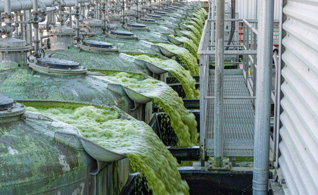
A rougher bank in continuous duty: each cell’s recovery budget is spent or saved at its rotor.
Suspension. The rotor pumps slurry down the draft tube and radiates it outward across the tank floor. Coarse particles that would otherwise settle stay in circulation, and the tank’s full volume stays live. When wear slows this action, sand accumulates from the corners inward; a half-sanded cell still froths convincingly while quietly processing less. The settled bed is lost metal until someone shuts down and digs it out.
Air shearing. Beneath the rotor, low-pressure air meets slurry, and blade edges chop it into bubbles. Bubble fineness is the arithmetic of recovery — finer bubbles mean more surface per volume of air, more attachment chances, better carrying into the froth. Fresh blades hold the design spectrum; rounded, worn blades make fewer, coarser bubbles that carry less and shed earlier. The flow physics is treated in depth in this guide to Rotor & Stator in Mechanical Flotation Cells, and its cost consequences in our article on Flotation Cell Rotor and Stator Wear Parts.
Mixing and transfer. The rotor’s turbulence disperses collector and frother through the pulp in seconds and keeps air holdup even across the tank. In most machine families its pumping action also transfers pulp to the next cell over a weir or through a communication port. Mixer and pump in one, decaying together on the same curve.
Power draw binds the story: as blades lose their working face and the clearance opens, the motor’s useful work falls, and the weekly power trend drops almost linearly with profile loss.
Benefits
- Recovery held at design— bubble size and suspension stay where the metallurgist set them.
- Planned maintenance— weighed rotors announce their own replacement dates.
- Power efficiency— motor energy goes into mixing, not churning an oversized gap.
- Downstream protection— cells that never sand out never slug the Thickeners behind them.
- Honest troubleshooting— with wear controlled, chemistry and feed get the blame they deserve.
- Procurement leverage— a plant with its own wear curve buys on schedule, not in emergencies.
Applications
Rotors serve copper, lead-zinc, nickel, gold sulphide, phosphate, lithium, and industrial mineral circuits. Roughers give them tonnage and coarse feed; cleaners demand bubble precision in delicate chemistry; scavengers ask them to recover what everyone else missed.
Demand keeps arriving. In mid-November 2026, Gunnison Copper reported high-grade copper-zinc intercepts at its Strong & Harris deposit in Arizona and confirmed flotation testwork to assess saleable copper and zinc concentrates with silver by-product. On November 11, 2026, Allonnia announced that its D-Solve process completed a three-month continuous pilot at Talon Metals’ Eagle nickel mine, cutting magnesia in nickel sulphide concentrate by up to 30% while lifting nickel grade about 2%. Cleaner concentrate targets and new flowsheets land, eventually, as more rotors on more shelves.
Material Comparison
| Property | Natural Rubber | Polyurethane | Ceramic Composite |
| Abrasion resistance | Good | Very good | Excellent at leading edges |
| Impact tolerance | Excellent — deflects | Moderate — may crack | Brittle under direct impact |
| Chemical resistance | Moderate | Very good | Very good |
| Profile retention | Fair | Good | Excellent |
| Relative cost | Lowest | Mid | Highest |
| Natural home | Coarse rougher feed | Cleaners, corrosive pulps | High-velocity blade tips |
Application Comparison
| Duty | Recommended Material | Why |
| Large rougher machines | Rubber, composite tips | Impact dominates; tips take velocity |
| Cleaner circuits | Polyurethane | Precision and chemistry dominate |
| Scavenger cells | Rubber or PU per data | Measured wear rate decides |
| Regrind-fed fine duty | PU or composite | Profile loss costs recovery most |
| High-air-rate machines | Composite on rotor | Extreme tip speed |
Industry Application Matrix
| Industry | Duty Character | Typical Material |
| Copper concentrators | High-tonnage roughing | Rubber with composite tips |
| Lead-zinc circuits | Multi-stage cleaning | Polyurethane |
| Gold sulphide plants | Mixed rougher and cleaner | Rubber roughers, PU cleaners |
| Phosphate plants | Sandy coarse feed | Rubber |
| Nickel sulphide | Fine, corrosive pulps | Polyurethane |
| Lithium circuits | Reagent-aggressive duty | Polyurethane |
Selection Guide
Choose the machine before the material. Confirm cell model, rotor diameter, hub bore, mounting pattern, blade count, and air pathway first — suppliers of Flotation Rotor & Stator Parts manufacture from OEM drawings, an original set, or the worn sample, and good photographs plus key dimensions turn quotes around in days.
Match material to duty with the tables above, then ask the supplier for two numbers: as-new weight, and the weight loss they recommend as the replacement trigger. Numeric answers mean you’re talking to someone who has watched these parts wear.
Check the feed too. Drifting Hydrocyclones upstream change the size distribution the rotor must suspend, and the resulting sanding gets blamed on the wrong part. Further back, Ball Mill Liners and grinding media set the grind flotation inherits. Diagnose the circuit, not just the cell.
Procurement Guide
A complete RFQ includes:
- Machine identification:cell model, family, generation or serial number.
- Geometry:drawings or worn sample; rotor diameter, hub bore, mounting pattern, blade count.
- Material specification:rubber, polyurethane, or composite; hardness range where relevant.
- Quantity and spare ratio:running sets plus shelf stock.
- Inspection requirements:dimensional report, as-new weight, hardness certificate, balance report for large rotors.
- Packaging and shipping:export-ready crating with humidity protection.
- Lead timeagainst the shutdown calendar.
Supplier evaluation is mostly documentation quality. Can they manufacture to drawings? Do material reports accompany delivery? Have they shipped crated polymer wear parts internationally? A mature aftermarket for Flotation Impeller & Stator sets exists because plants ask these questions — the suppliers left standing are the ones with answers on paper.
Failure Analysis
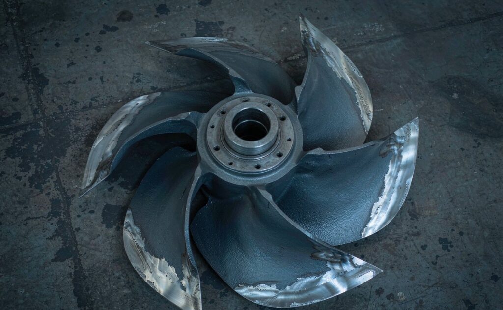
The classic signature: rounded edges, thinned blades, and a gap no longer matching the drawing.
| Problem | Possible Cause | Recommended Solution |
| Premature edge rounding | Tramp metal, oversize feed | Improve screening; review classification |
| Cracked polyurethane | Impact beyond tolerance | Reassign duty to rubber |
| Rubber debonding | Bond defect or chemical attack | Demand bond data; audit reagents |
| Uneven circumferential wear | Misalignment, bowed stator | Verify mounting flatness at refit |
| Poor air dispersion | Worn blades, blocked airway | Gauge clearance; inspect airway |
| Vibration after refit | Imbalance, poor hub fit | Require balance report; verify fit |
| Persistent sanding | Drive or air fault | Check power draw and aeration first |
| Short campaign life | Material mismatch | Re-specify material from wear data |
Maintenance Guide
Daily, operators listen — cell sound changes before recovery numbers do. Weekly, power draw and air rate go into the log against baseline. At each planned pull, the rotor is weighed, gauged, and photographed against the as-new record made at installation. Replacement triggers — 15–20% weight loss or doubled clearance — are standing rules decided in the office, not argued on the platform at midnight. Shelf stock holds a matched set for each large machine, rotated oldest-first and stored indoors away from sunlight and ozone.
Case Study
Customer Type: Mid-size copper concentrator, South America
Ore Type: Copper sulphide with pyrite, moderately abrasive
Operating Conditions: Four rougher machines on rubber rotor sets, 4 mm design clearance
Problem: Recovery drifted about one percentage point over two months; the last machine’s froth turned visibly coarser
Solution: Weighed all four rotors and gauged clearances at the next shutdown. The end-machine rotor had lost 22% of its mass with clearance doubled; two more sat near 15%. Three rotors replaced with matched stators in one planned shutdown, the fourth at the following window.
Result: Recovery returned to baseline within days and held; end-machine power draw fell back to its installed value. The plant now orders against its own measured wear curve instead of a generic supplier estimate.
FAQ
Is a rotor the same as an impeller?
In flotation machinery, yes — both name the rotating submerged component that suspends slurry and shears air. Some vendors reserve “impeller” for the blade assembly and “rotor” for blade-plus-hub. When ordering, describe the part and its dimensions rather than debating vocabulary.
How does rotor wear show up in the plant?
First as falling power draw at stable slurry, then as coarser froth bubbles, then as slow fine-particle recovery drift while concentrate grade holds. The sequence is quiet and deceiving, which is why weight records and clearance gauges — not froth appearance — should drive replacement.
How long does a rotor last?
Tonnage, abrasivity, and material set the clock together. Rubber rougher rotors often run many months; polyurethane cleaners can run longer. Replace at 15–20% mass loss or doubled clearance, whichever arrives first, using your own measured curve.
Can a worn rotor be repaired?
Sometimes — relining a large rotor with a sound insert and intact geometry can be viable as planned refurbishment. Past 20% mass loss the profile is gone and coating cannot restore it. Repair rarely rescues a part run to failure economically.
Should rotor and stator be replaced together?
Yes. They wear as a matched system, and mixing a new rotor with a half-worn stator lands the clearance somewhere neither part was designed for. Record the pair’s serial numbers against the machine for cleaner wear data.
What information makes a rotor RFQ complete?
Machine model and family, drawings or worn sample, dimensions, material and hardness spec, quantities with spare ratio, inspection requirements, packaging, and lead time. Complete enquiries price better because the supplier isn’t pricing your omissions.
Does rotor speed matter as much as condition?
Machines are designed around a tip speed balancing bubble shearing against sanding risk and power draw. A worn rotor at design speed underperforms a healthy one at the same setting. Fix the wear first, then tune speed and aeration.
What causes uneven rotor wear?
Misalignment, a bowed stator face, or a hub fitted off-center drives one blade side harder than the other. The wear pattern is diagnostic — photograph removed rotors before scrapping, and the pattern usually points at the fitting error that caused it.
Conclusion
The rotor touches every part of the flotation recovery mechanism — suspension, bubble generation, mixing, reagent dispersion, and inter-cell transfer — and all those functions decay together as polymer wears off the blade edges. The remedy costs a scale, a gauge, and a spreadsheet. Weigh each rotor, watch the power trend, replace on evidence, and buy from suppliers who document what they ship. Plants that manage the rotor as a measured consumable hold recovery flat and turn wear parts from a crisis into a schedule.
Related Articles
Related Products
- Flotation Cell Machines
- Custom Rotor and Stator Manufacturing
- Impeller and Stator Replacement
- Rotor and Stator Spare Sets
- XJK Type Flotation Machine
- SF Type Flotation Machine
Related Technical Guides
- Rotor-Stator Wear Parts and Maintenance Cost
- Rotor-Stator Flow Patterns Guide
- Hydrocyclone Wear Zones and Materials
- Hydrocyclone Underflow Causes and Fixes
- Fine Screening with Polyurethane Panels
Related Buyer Guides
Related Comparison Articles
Contact
Annie Lu
Email: annie.lu@huataogroup.com
WhatsApp / WeChat: +86 18032422676
Website: www.tufflexscreen.com
HTL Solutions manufactures rubber, polyurethane, and ceramic-composite flotation rotors and matched stators to OEM drawings or from worn samples, shipping weight, hardness, and dimensional documentation with every order.
 admin
personal profile