What Is a Flotation Rotor and Stator and How Do They Work?
-
 admin
- 17 Nov, 2026
Quick Answer
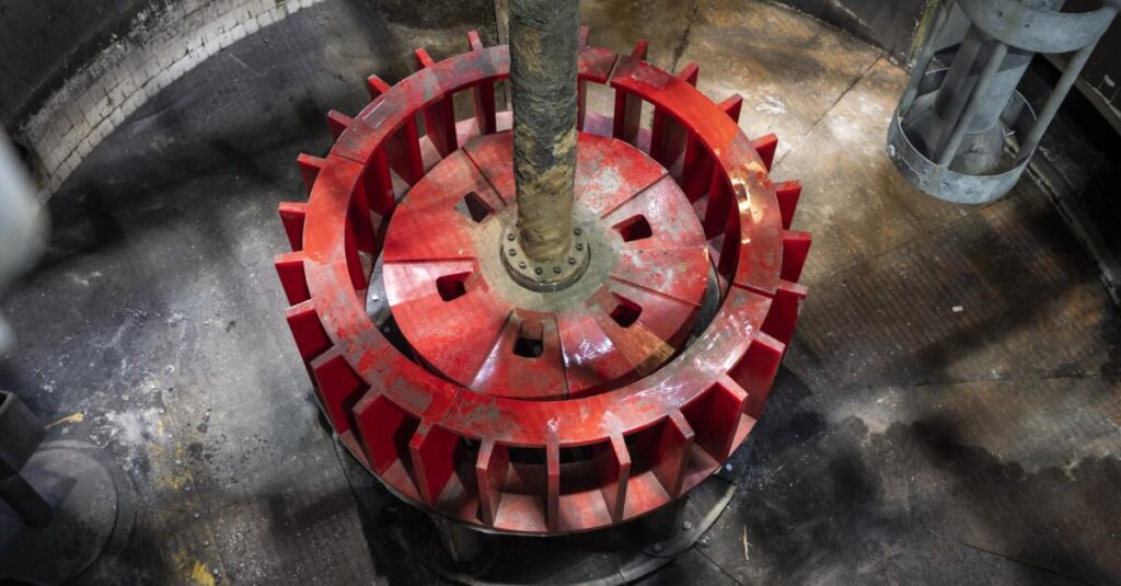
A flotation rotor and stator are the moving and stationary halves of the agitating mechanism inside a mechanical flotation cell. The rotor — the impeller bolted to the bottom of the drive shaft — spins at peripheral speeds of roughly 5–10 m/s, throwing pulp outward and drawing or receiving air. The stator, a fixed ring of blades around it, shears that air-pulp mixture into fine bubbles and removes the swirl before it reaches the froth. Recovery, in a very real sense, is manufactured in the centimetres between the two.
Key Takeaways
- The rotor suspends, aerates and creates particle-bubble contact; the stator shears bubbles, kills swirl and protects the froth zone.
- Bubble surface area flux — the kinetic currency of flotation — is produced at the rotor-stator interface, so its geometry and clearance decide recovery ceilings.
- Rotor and stator are consumable wear parts: profile wear of tens of millimetres on large mechanisms is normal before replacement.
- Material selection — natural rubber, polyurethane, rubber-ceramic composite — trades impact tolerance against profile stability.
- Condition signals (recovery drift, falling air draw, rising blower pressure, sanding) appear long before audible changes.
Summary Table
| Aspect | Rotor | Stator |
| Role | Pump, aerate, suspend, contact | Shear, redirect, stabilise |
| Speed | 5–10 m/s peripheral | Stationary |
| Wear signature | Profile rounding, blade thinning | Edge grooving, blade deflection |
| Materials | Rubber / PU / ceramic composite | Rubber / PU / ceramic composite |
| Change trigger | Clearance or profile limit | Same, usually paired |
Definition: What Counts as a Flotation Rotor and Stator
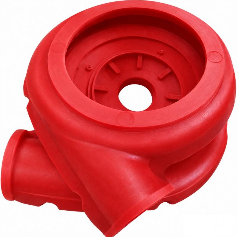
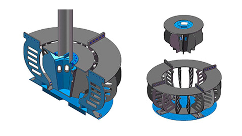
Mine-site language is specific here. “Impeller” and “rotor” are synonyms for the rotating assembly: a central disc, radial or curved blades, and often a protective disc cover that takes the first abrasive hit. The stator — also called a diffuser or disperser — is the stationary ring of blades surrounding the rotor, either overhung on the shaft or bolted to the tank floor. Air enters the mechanism two ways: self-aspirating machines (the classic XJK and SF families) use the rotor’s own suction to pull air down the hollow shaft, while forced-air machines (the XCF/KYF family and most large modern cells) receive low-pressure blower air through the shaft or a standpipe. Both designs converge on the same dispersion event: air meets pulp in the gap, and the gap’s geometry decides what comes out.
Working Principle: Where Recovery Is Actually Made
Follow one particle through the mechanism and the division of labour becomes clear.
Suspension. The rotor’s pumping action keeps the whole solids inventory moving. Settling is the first failure of a tired mechanism: sand pools in tank corners, effective volume shrinks, and coarse values quietly report to tailings.
Aeration. Air entering the rotor zone is torn into bubbles of roughly 0.5–2 mm. That band is not arbitrary — it matches the buoyancy and stability window that floats sulphide minerals efficiently. Finer bubbles lack lift; coarser ones burst and shed particles.
Contact. The turbulent field at the rotor edge is where particle-bubble collisions happen at industrial rates. Most of a cell’s recovery is won within centimetres of the rotor.
Stabilisation. The stator’s blades intercept the tangential swirl and convert it into vertical circulation. Without this, vortexing tears the froth from below and detaches already-floated particles. The quiescent zone under the froth is the stator’s gift to the recovery curve.
Put numbers on it. A 2.5 m rotor at 7 m/s peripheral speed turns a large cell thousands of times per shift. Every revolution stages a fresh population of bubbles into the pulp above. If the bubble population averages 1 mm instead of 1.5 mm because the clearance has opened, the bubble surface area per unit air drops roughly by a third — and the kinetics slow accordingly. Nothing breaks; the machine simply gets slower at the only job it has. This is why clearance limits are stated in millimetres and enforced in change-outs rather than left to feel.
Benefits: What a Healthy Mechanism Buys
- Recovery leverage.A mechanism in spec produces abundant, fine bubbles and full suspension — the two conditions every flotation model assumes.
- Energy efficiency.Fresh profiles pump with less slip, so target circulation costs less power.
- Shutdown predictability.Wear is gradual and measurable; change-outs land inside planned windows instead of emergency ones.
- Retrofit upside.New-generation profiles fitted to older tanks can lift recovery without civil works.
Applications: Which Machines Use This Mechanism
Every mainstream mechanical family runs on the same principle. Self-aspirating mid-size cells (XJK, SF) dominate smaller plants and older installations; forced-air tank cells (XCF/KYF and their international cousins) dominate large new builds, including the Jameson-type contact cells now being ordered by new projects — Brazil’s Cabacal copper-gold development placed long-lead orders for Jameson cells in November 2026, and Arizona’s Gunnison Copper flagged flotation test work the same week to define its processing route for a high-grade copper-zinc zone. The machine forms differ; the wear economics of the mechanism do not. What does change with chemistry is everything upstream of the collision: flotation reagent feeders meter the collectors and frothers that decide how hydrophobic each particle is when it reaches the mechanism, and a stable reagent regime makes the wear cycle readable. A plant that bounces its reagent scheme is a plant whose mechanism logs look noisy, because grade-recovery targets move underneath the hardware.
The Air System Around the Mechanism
The mechanism shares its job with the air circuit, and the two must be trended together. In self-aspirating machines — the classic XJK flotation cell and SF flotation cell — the rotor’s own suction pulls air down the hollow shaft, so drawn air volume is a direct readout of mechanism health: as the profile rounds, suction weakens and the flowmeter falls. In forced-air machines such as the XCF/KYF flotation cell, a blower supplies the air and the same wear shows the opposite way — blower pressure drops because worn clearances let air escape un-sheared. In both cases the mechanism is the sensor; the air circuit is its dial.
Where the Mechanism Sits in the Flowsheet
Upstream, the liberation work belongs to grinding mills and their consumable mill liners; size control belongs to classification. Downstream of roughing, cleaner and scavenger stages reuse the same mechanism principle at different intensities — cleaners run gentler, with finer bubble populations prioritised over raw suspension power. Non-sulphide streams bypass flotation entirely: iron-bearing minerals go to magnetic separators, and coarse high-contrast feeds suit gravity machines. The point of the map is the boundary condition: everything the mechanism receives — size, liberation, chemistry — is decided before it, and everything it delivers is graded after it. Its wear budget deserves the same planning rigour as any other consumable in that chain.
Material Comparison
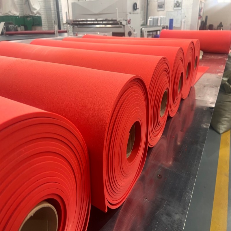
Natural rubber. The workhorse. It deflects under particle impact, shrugging off the cracking that kills stiffer materials, and patches easily in situ. Its compromise is dimensional stability: softer compounds profile-round faster, opening the rotor-stator clearance sooner. Best for corrosive duties with fine-to-medium feed.
Polyurethane. Holds its moulded profile far longer, which keeps the clearance — and therefore bubble size — stable through the campaign. The trade is impact tolerance: very coarse, sharp feeds can initiate cracks. Best for abrasive, high-tonnage duties where the feed is well screened.
Rubber-ceramic composite. Ceramic tiles set into the highest-velocity zones of the rotor or stator extend life where ore is brutal and cells are large. The unit price is higher and the inspection list gains one item: bond integrity. A detached tile becomes fast-moving debris in the circuit.
Suppliers moulding the flotation impeller & stator range typically quote expected profile loss per thousand duty hours for each material against a stated duty. Those numbers are worth demanding in writing: they turn the material conversation from adjectives into arithmetic, and they set the inspection interval — the campaign length should fit inside the quoted life with margin, not sit exactly on it.
| Material | Impact tolerance | Profile stability | Watch for |
| Natural rubber | High | Moderate | Rounding of blade edges |
| Polyurethane | Moderate | High | Impact cracking |
| Ceramic composite | High (localised) | Highest | Bond failure |
Application Comparison
| Duty | Mechanism priority |
| Rougher, coarse siliceous feed | Composite or PU; short inspection cycle |
| Cleaner, fine gentle feed | Rubber; long cycles acceptable |
| Self-aspirating small cells | Rubber; weekly drawn-air checks |
| Large forced-air cells | Composite zones; blower-pressure trending |
Industry Application Matrix
| Industry | Mechanism emphasis |
| Copper | High-tonnage roughing; abrasion-driven materials |
| Gold | Fine-bubble cleaners; profile stability |
| Lead-zinc | Multi-stage circuits; staged materials |
| Phosphate / potash | Coarse flotation; impact-resistant parts |
Selection Guide: Decide From the Duty
Sequence the decision: confirm size distribution and abrasiveness, check chemistry (pH, reagents that attack the polymer), then match material to impact-versus-abrasion balance, then confirm profile against OEM drawings or a measured sample. Insist on a written clearance limit from the supplier so the next change-out has an objective trigger rather than a subjective one. Only then negotiate price — because a cheaper part that rounds early costs more in unrecovered metal than it saves in cash.
Procurement Guide: What to Send and Ask
Prepare: cell model and size, rotor diameter, profile drawing or worn sample, material preference and duty description (feed size, tonnage, solids density, pH). Ask: expected wear life per material, quality control on profile moulding, packing and hardware completeness, and delivery against the shutdown date. Reputable aftermarket suppliers — working from the flotation rotor & stator parts range — answer all four without prompting.
Failure Analysis: Four Modes, One Root Cause
All four common failures trace back to wear environment or installation:
- Profile rounding— clearance opens, bubbles coarsen, fine recovery leaks first.
- Blade loss— sudden imbalance, vibration and rising power draw.
- Bond failure(composites) — detached tiles circulate; inspect bonds at every change.
- Hardware neglect— a fretted rotor key lets the assembly walk on the shaft.
The condition-monitoring playbook that catches all four is described in the rotor and stator wear parts guide.
Maintenance Guide
- Weekly:log air draw or blower pressure and power draw per cell; walk the row and listen.
- Monthly:physical clearance checks on a rotating sample of cells; photograph profiles.
- At change-out:record profile loss against duty hours; verify shaft runout and key fit.
- Annually:align couplings, verify tank liners, refresh the spares holding against the wear trend.
Case Study: Half a Point, Two Months, One Shift
A concentrator’s cleaner string lost half a point of recovery over two months while feed grade and reagent regime held steady. The reagent sheet offered no explanation; the mechanism log did — drawn air on the cleaner cells had slipped several percent. Inspection found rotor profiles past the clearance limit on three of six cells. One shift per cell, all six replaced, recovery restored within a day of the last change-out. The cost of the assemblies was a fraction of the metal already lost.
FAQ
Q: Is an impeller the same as a rotor?
Yes — same part, different dialect. “Rotor” is the usual site term for the wear assembly.
Q: What clearance should a rotor-stator run?
OEM-specific, but suppliers state a limit per profile. The operating rule: measure, don’t guess, and replace at the stated limit.
Q: Can I mix materials — PU rotor on a rubber stator?
Technically yes, and mixed sets are common in staged upgrades. Confirm the clearance pair remains in spec as each wears at its own rate.
Q: How much recovery does a worn mechanism cost?
Plants report one to three percentage points when mechanisms run far past their limit, with fine fractions suffering first.
Conclusion
A flotation rotor and stator convert chemically prepared pulp into a separation: the rotor pumps, aerates and contacts; the stator shears, straightens and protects. Everything else in the cell — tank, launder, froth — depends on that core doing its work inside a clearance measured in millimetres. Trend the mechanism’s signals, choose the material for the duty, and replace on measurement rather than faith; the mechanism is the process, and its upkeep is the highest-leverage maintenance decision in the flotation section. For material options and fit guidance across cell families, start from the flotation equipment hub and the flotation cells catalogue.
Related Articles
- Flotation Cell Rotor and Stator Wear Parts: How They Control Recovery, Flow and Maintenance Cost
- Rotor & Stator in Mechanical Flotation Cells: The Heart of Efficient Mineral Flotation
Contact
Contact: Annie Lu
Email: annie.lu@huataogroup.com
WhatsApp / WeChat: +86 18032422676
Website: www.tufflexscreen.com
HTL Solutions (Tufflex brand) manufactures rubber, polyurethane and ceramic-composite rotor-stator assemblies for XJK, SF and XCF/KYF families. Send cell model, profile sample and duty description for a material recommendation and quotation.
 admin
personal profile