Prevent Material Buildup on Return Rollers: A Field Guide to Carryback Control
-
 admin
- 09 Nov, 2026
Quick Answer: Return roller buildup is carryback that survived the discharge point, delivered daily to the return run. Control it in sequence: a primary cleaner at the head pulley for the bulk, a secondary cleaner for the residual film, a V-plow before the tail pulley for loose debris, containment at the loading zone, and prompt replacement of seized rollers. Trace the source from the deposit pattern first, because spillage, water and tracking faults mimic carryback and defeat any blade.
What Is Return Roller Buildup?
Carryback is the material that stays attached to the belt after the bulk discharges at the head pulley. On the return run, the carrying surface faces downward, and whatever survived the cleaners travels home, dropping onto floors or transferring to return rollers as uneven deposits. As deposits grow, the roller’s effective diameter changes, belt support and friction shift, and the symptoms multiply: mistracking, edge wear, bearing contamination, and eventually a seized roller grinding a flat spot under a moving belt.
The deposit on the roller is a delivery report. The address is upstream, and the treatment lives there too.
Key Takeaways
✔ Deposits heaviest near the head pulley indict the cleaners; mid-run buildup indict nearby transfers.
✔ A V-plow guards the clean side; it never replaces primary and secondary cleaning.
✔ Wet, sticky fines need a matched blade compound, and more pressure is the wrong answer.
✔ Cleaning performance is measurable: blade life, rollers cleaned, labour hours.
✔ Seized rollers get replaced, and the cleaning system gets investigated before the next swap.
Summary Table
| Item | Description |
| Function | Stop material from reaching and adhering to return rollers |
| Sequence | Primary cleaner, secondary cleaner, V-plow, containment |
| Key metric | Rollers cleaned per week; blade life between changes |
| Diagnosis | Deposit pattern along the return run |
| Outcome | Occasional checks instead of weekly scraping |
Definition
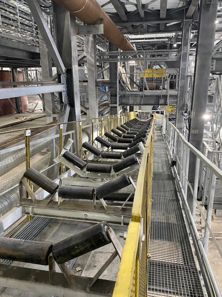
Wet fines on a return roller
The deposit is the symptom; the head pulley is the address.
Return roller buildup is the accumulation of conveyor material on the rollers supporting the lower belt run. It forms from carryback dropping or transferring off the belt, from spillage entering the return side, and from environmental contamination such as water and nearby process leakage. Each source leaves a characteristic pattern, which makes buildup one of the most diagnosable problems on a conveyor, provided someone walks the return run and reads it.
Working Principle
Carryback changes character along the belt, and the cleaning sequence follows that change.
At the head pulley, the primary cleaner faces the material at its thickest. Polyurethane blades dominate here because they flex around tramp metal, forgive imperfect belt surfaces and protect splices. Positioning, tensioning and compound matching decide whether the blade peels material or just smooths it.
Downstream, the secondary cleaner faces the film: thinner, often wetter, more adhesive. This stage matters most on wet iron ore, clay-rich minerals and coal fines, where a single scraper leaves an adhesive layer that binds to everything it touches. Blade material, angle and pressure must respect the belt’s mechanical splices, and pressure follows the manufacturer’s numbers rather than the belief that harder means cleaner.
The return side has a different problem and its own device. Loose material arrives on the clean side through spillage and transfers and travels toward the tail pulley, where it grinds lagging and traps under the belt. A V-plow diverges that debris toward the edges before the pulley. It is a guard for the clean side, and specifying it as a cure for carryback is the most common return-side mistake in the industry.
Containment and condition complete the system. Skirting that seals without grooving keeps the loading zone where it belongs. Prompt roller replacement keeps the run rotating. Tracking kept honest keeps deposits from gathering on one side, and a belt tracker manages residual drift only after the mechanical faults are fixed.
Benefits
- Roller cleaning shifts from weekly routine to occasional verification.
- Bearing contamination and roller seizures decline with the deposits.
- Tracking stabilises as roller diameters stay even.
- Cleanup labour becomes measurable, then smaller.
- Tail pulley lagging survives longer without trapped material.
Applications
The problem concentrates where material is wet or fine: iron ore with moisture, clay-rich ore bodies, coal handling, washed aggregate. Season and ore source change the severity, which is why cleaning equipment should be selected for the most demanding conditions reasonably expected, with adaptation as ore properties shift. Downstream, the same fines feed screening and classification, where stable feeding depends on the same control.
Diagnosis deserves its own paragraph, because it is the step most sites skip and the reason most cleaning investments disappoint. Walk the return run and record where deposits first appear. Heaviest near the head pulley points at carryback, and the cleaning sequence is the target. Contamination beginning mid-run points at nearby transfers, overhead spillage and water; more blades at the head will change nothing. One-sided deposits point at tracking or uneven blade contact. The material itself adds evidence: fine dry powder suggests inadequate fine removal, wet sticky layers suggest moisture-driven adhesion, and a noisy stationary roller has graduated from deposit to failure. Twenty minutes of pattern reading protects the budget from being spent on the wrong stage.
Material Comparison
| Component | Options | Return-side relevance |
| Primary blade | Polyurethane | Flexes around tramp; splice-friendly |
| Secondary blade | PU or carbide tip | Carbide for fine, abrasive residue |
| V-plow blade | Rubber or PU | Diverts loose debris before the tail |
| Return roller | Steel vs rubber-disc | Rubber-disc limits contact retention |
| Skirting | PU vs rubber | Containment at the source |
Application Comparison
| Location / condition | Dominant source | Response |
| Deposits heaviest near head | Carryback | Cleaner pair rebuild |
| Wet sticky layers | Moisture adhesion | Matched compound, documented pressure |
| Mid-run contamination start | Spillage, water | Transfer and drainage repair |
| One-sided deposits | Tracking, blade alignment | Alignment before hardware |
| Seized rollers | Bearings past saving | Replacement and frame verification |
Industry Application Matrix
| Industry | Typical contamination | First investment |
| Iron ore mining | Wet fine ore | Cleaner pair rebuild |
| Coal handling | Coal fines | Secondary cleaning |
| Aggregate | Washed fines | V-plow and containment |
| Cement | Sticky additives | Blade material upgrade |
| Ports | Mixed spillage | Return-side programme |
Selection Guide
- Map the deposits: where they start, how they spread, which side.
- Rebuild the head-end sequence: primary and secondary, pressures documented.
- Guard the tail: V-plow ahead of the pulley, with debris allowed to escape.
- Contain the source: skirting and chute work before more hardware.
- Refresh the rollers: replace seized units, verify surrounding alignment.
- Measure: blade life, rollers cleaned per week, labour hours.
Procurement Guide
Buy the sequence against material data. The enquiry package carries belt width and speed, splice type, material and moisture range, tonnage, existing cleaner dimensions and installation photographs. Test each bidder with three questions: which blade compound for our wettest ore, and why; what pressure documentation accompanies the proposal; can primary, secondary, V-plow and rollers arrive as one matched package with interface responsibility in one place. A supplier who quotes from the photographs is engineering the return side; one who quotes from a part number is shipping steel toward it.
Failure Analysis
| Problem | Possible Cause | Recommended Solution |
| Deposits return within days | Cleaning inadequate at source | Rebuild primary/secondary stages |
| Wet clay survives cleaning | Wrong blade or pressure | Match compound to moisture data |
| Buildup starts mid-run | Spillage or water ingress | Repair transfers, skirting, drainage |
| One-sided deposits | Tracking or blade misalignment | Correct alignment before hardware |
| Rollers seize repeatedly | Bearings past saving | Replace and verify adjacent frames |
| Blade wear in weeks | Overtension, abrasive mismatch | Reset pressure, review compound |
Maintenance Guide
Daily, observe the return belt after the head pulley from designated safe positions. Weekly, check blades for wear and tensioner function, rollers for noise and rotation. Monthly, review deposit patterns and cleanup labour, and adapt to ore changes: a cleaner set for dry aggregate underperforms in a wet season. Every intervention is recorded. Physical inspection, cleaning and replacement happen only after isolation and lockout; nothing is ever scraped or adjusted on a moving conveyor.
Case Study
Customer Type: Iron ore processing plant, stockpile reclaim conveyor.
Material: Wet hematite fines with clay content, variable moisture.
Operating Conditions: 1400 mm belt, single primary cleaner, no secondary stage.
Problem: Return rollers scraped weekly; three rollers seized in six months; deposits heaviest near the head.
Solution: Secondary cleaner installed with pressure documentation; V-plow added before the tail pulley; seized rollers replaced and adjacent frames verified.
Result: Roller cleaning fell from weekly to occasional checks, with no further seizures over the following two quarters, per the site’s maintenance log.
FAQ
- Why do return rollers keep getting dirty after cleaning?
Because the source is upstream. Carryback surviving the head pulley re-coats them within days. Fix the cleaning sequence and the rollers.
- Can rubber-disc return rollers solve buildup?
They reduce contact and retention in some duties but remove no carryback. They complement a cleaning system; they never replace one.
- Polyurethane or carbide cleaner blades?
Polyurethane for primary duty and splice protection; carbide tips for secondary cleaning of fine, abrasive residue. Match to the material.
- Where should the V-plow be installed?
On the inside of the return belt ahead of the tail pulley, positioned so diverted debris escapes. It guards the clean side only.
- How do we find the contamination source?
Read the pattern: near the head means carryback, mid-run means nearby spillage, one-sided means tracking or blade alignment.
- How is cleaning performance measured?
Blade life, rollers needing cleaning per week, labour hours, and weighed carryback samples before and after changes under comparable conditions.
- What if cleaning fails when the ore turns wet?
Expected behaviour. Cleaners should be selected for the most demanding conditions, and seasonal changes justify additional stages or specialised blades.
- Is water-based washing worth considering?
Only after assessing water supply, drainage, wastewater handling and corrosion risk, and only where mechanical cleaning genuinely cannot cope.
- How often should the system be inspected?
Observation daily from safe positions, blades and rollers weekly, deposits and labour reviewed monthly, tightened for wet abrasive duty.
Conclusion
Return roller buildup is a message from the head pulley, delivered in clay. The deposits announce that carryback survived discharge, and roller-side scraping never answers it. Read the deposit pattern to find the source, rebuild the cleaning sequence with documented pressures, guard the tail with a V-plow, contain the spillage where it starts, and keep the return run rotating. Measure blade life and labour hours, and the weekly scraping routine ends where it should have started: one revolution after the discharge point.
Related Articles
Related Products
- Conveyor Belt Cleaner / Scraper
- Polyurethane Conveyor Belt Cleaner Blades
- Mining Secondary Belt Cleaner
- Conveyor Idlers & Rollers
- Conveyor Belt Skirting
Related Technical Guides
- Hydrocyclone Wear: Root Causes, High-Wear Zones & Material Solutions
- Flotation Cell Rotor and Stator Wear Parts
- Improve Fine Screening Efficiency with Polyurethane Screen Panels
- Hydrocyclone Underflow Too Wet? 6 Causes & Fixes
- Rotor & Stator in Mechanical Flotation Cells
Related Buyer Guides
Related Comparison Articles
Contact
Annie Lu
Email: annie.lu@huataogroup.com
WhatsApp/WeChat: +86 18032422676
Website: www.tufflexscreen.com
Tags:
 admin
personal profile