Reduce Conveyor Belt Wear in an Iron Ore Mine: A Field Engineer’s Guide
-
 admin
- 07 Nov, 2026
Quick Answer: Reduce conveyor belt wear in an iron ore mine by controlling four mechanisms in order: impact at the loading zone, sliding abrasion at feed entry, cutting from trapped particles, and edge wear from mistracking. Support the loading zone, clean the return side, seal the skirt line correctly, and match the belt cover grade to the dominant mechanism.
What Is Conveyor Belt Wear in Iron Ore Service?
Conveyor belt wear in iron ore service is the progressive loss of cover rubber and, eventually, carcass integrity caused by the material the belt carries and the conditions it carries it through. Iron ore concentrates the problem: sharp particles, high lump mass, abrasive fines and continuous high tonnage. A belt that would run for years on gravel can lose its cover in months on hematite if the loading zone is wrong.
Wear is not random. It follows physics, and physics leaves fingerprints. Read the fingerprints and the belt tells you what is hurting it.
Key Takeaways
✔ Impact damage concentrates below the chute; support beats thickness.
✔ Sliding abrasion happens where material accelerates to belt speed.
✔ Longitudinal grooves mean trapped particles, somewhere specific.
✔ Edge wear points to tracking and loading, never to the belt itself.
✔ Cover-thickness-per-tonne is the most honest wear metric on site.
Summary Table
| Item | Description |
| Function | Protect the belt cover and carcass through the full conveying cycle |
| Main wear mechanisms | Impact, sliding abrasion, cutting, mistracking |
| Key components | Impact beds, cleaners, skirting, trackers, idlers |
| Measurement | Cover thickness at fixed points vs cumulative tonnage |
| Benefits | Longer belt life, planned replacements, lower downtime |
Definition
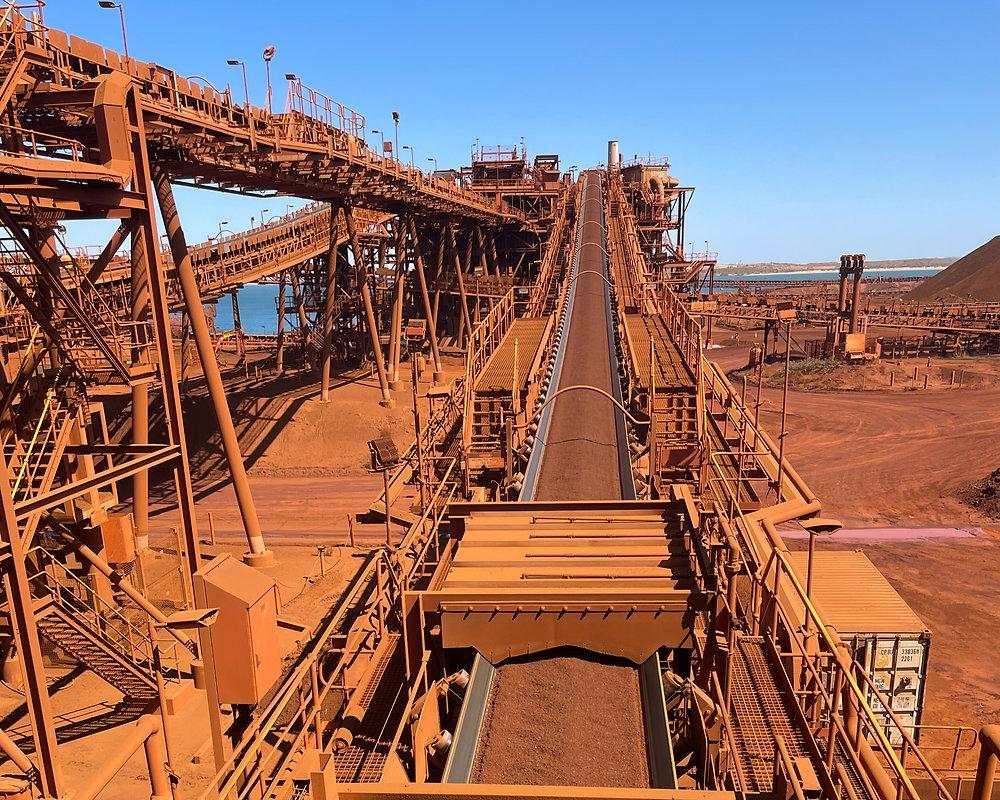
Iron ore conveyor loading zone
In iron ore service, the loading zone decides belt life more than the belt specification does.
Belt cover wear is measured in millimetres of rubber lost; belt failure is measured in unplanned downtime. The two are connected but not identical. A cover can wear uniformly for years and reach its limit predictably, or it can fail locally in weeks where a mechanism concentrates energy in one spot. The engineering task is to convert local concentration into uniform, predictable loss.
Working Principle
Four mechanisms do the damage, and each has a distinct signature.
Impact is kinetic energy delivered vertically. A lump of iron ore falling 3.5 metres into a 1600 mm belt deposits enough energy to deform the carcass, especially where the belt spans freely between idlers. The fix is geometric: reduce drop height where possible, and spread the remaining energy over continuous support. A heavy-duty impact bed does exactly this, replacing the free span under the chute with low-friction bars that let the belt slide while the bed absorbs the load.
Sliding abrasion is a velocity-difference problem. Material landing nearly vertically must be accelerated to belt speed, and while it accelerates, sharp particles drag across the cover. Research on granular transfer flow shows feed rate, particle size, belt speed and chute geometry all shape this wear. The countermeasure is chute design: land the stream near belt speed, centred, with the minimum possible sliding distance.
Cutting and gouging need three participants: a sharp particle, a stationary surface, and the belt between them. Trapped lumps at the skirting, damaged chute liner plates, protruding fasteners, each cuts its own groove. This is why grooves are diagnostic gold: they are always local, and the cause is always nearby.
Mistracking edge wear is self-inflicted. The belt runs against the skirtboard or frame, and the edge grinds away. Off-center feeding, seized conveyor idlers, pulley misalignment and material buildup are the usual drivers. A belt tracker manages the symptom; the alignment work cures it.
Benefits
- Predictable belt life: replacement becomes a planned shutdown item, not an emergency.
- Lower lifetime cost: support and cleaning components cost a fraction of a belt.
- Better sealing: a stable, supported belt line lets skirtingseal with light contact.
- Cleaner return side: effective cleaning protects rollers and pulleys downstream.
- Data for decisions: wear-per-tonne converts maintenance into engineering.
Applications
The mechanisms are identical across mining conveying, but intensity varies. Primary crusher discharge in iron ore is the highest-energy application in the plant; stockpile reclaim feed is moderate; plant transfer points vary with drop geometry. Downstream of conveying, the same ore continues through screening and classification stages, and every transfer between those stages is another loading zone with its own wear budget.
Cover-thickness measurement deserves its own paragraph, because it is the difference between managing wear and reacting to it. Choose fixed measurement stations: one below the primary transfer, one at mid-run, one before the discharge pulley. Mark them physically, not just on a drawing. Measure with the same gauge, at the same belt positions, and log the value with operating hours and cumulative tonnage. After two or three cycles the site has something almost no supplier can argue with: its own abrasion curve, under its own ore, on its own conveyor. That curve settles disputes about blade compounds, skirting materials and cover grades faster than any datasheet.
Material Comparison
| Component | Material options | Behaviour in iron ore service |
| Cleaner blades | Polyurethane | Flexes around tramp, protects the cover; pressure-sensitive |
| Cleaner blades | Tungsten carbide tipped | Outlasts PU in heavy duty; less forgiving of trapped metal |
| Impact bar surface | UHMW-PE | Lowest friction; protects the bottom cover |
| Impact bar core | Rubber, various hardness | Absorbs energy; hardness matched to lump size |
| Skirting | Rubber vs polyurethane | PU holds a bevel longer; rubber forgives rough belts |
| Belt cover | DIN 22102 Y / X / W | W for abrasion, X for combined damage; never a fix for tracking |
Application Comparison
| Location | Dominant mechanism | Engineering response |
| Primary crusher discharge | Impact | Continuous support, shortened drop |
| Secondary transfer | Abrasion + cutting | Chute redesign, cleaner overhaul |
| Head pulley discharge | Carryback | Primary + secondary cleaning |
| Return run | Buildup damage | V-plow before the tail pulley |
| Long overland runs | Mistracking drift | Trackers plus alignment audit |
Industry Application Matrix
| Industry | Ore / material | Leading mechanism | Notes |
| Iron ore | Hematite, magnetite | Impact + cutting | Highest lump energy in mining |
| Copper | Abrasive concentrate | Abrasion | Fine, sharp, high tonnage |
| Gold | Crushed ore, slurry-adjacent | Carryback | Moisture drives stickiness |
| Coal | ROM coal | Spillage and buildup | Less cutting, more fouling |
| Aggregates | Crushed stone | Impact | Oversize lumps at secondary feeds |
Selection Guide
Match the component to the measured condition, and never to the catalogue photo.
- Map the wear: one month of marks, photographed and classified by mechanism.
- Size support to energy: impact bedbar spacing and rubber hardness follow lump size and drop height.
- Set cleaning in sequence: a primary bladeat the head pulley, a secondary downstream, each at documented pressure.
- Seal with light contact: skirting should drop as it wears, not press harder as it wears.
- Protect the return side: loose material before the tail pulley is what V-plows are for.
- Choose the cover last: grade W earns its cost only once the first five are right.
Procurement Guide
Specify with data. Belt width, speed, tension rating and splice type; ore lump distribution, hardness and moisture; drop heights and chute trajectories; photographs of every worn location. A supplier who quotes from that package is engineering; one who quotes from the part number is selling. Ask every bidder how their polyurethane cleaner blades behave at your splice type, and ask for the pressure-setting documentation in writing.
Failure Analysis
| Problem | Possible Cause | Recommended Solution |
| Deep local damage below chute | Excess drop energy | Re-size support, shorten drop |
| Longitudinal grooves | Trapped particles | Inspect skirting gap, clamp bars, liners |
| One-sided edge wear | Off-center feed, seized idlers | Correct loading, replace rollers |
| Cover glazing and heat | Cleaner over-pressure | Reset to manufacturer limits |
| Return-side pitting | Carryback grinding rollers | Improve secondary cleaning |
| Rapid skirt wear with grooving | Trapped ore at the seal | Widen gap, clear buildup |
| Splice damage | Cleaner incompatible with splice | Match blade and pressure to splice type |
| Tracking instability | Worn structures, poor loading | Alignment audit before tracker tuning |
Maintenance Guide
Daily, walk the run: tracking, spillage, noise, visible damage. Weekly, isolate and inspect: cleaner blades, skirting contact, impact bars, accessible idlers. Monthly: chute liners, alignment, the wear map update. Every shutdown: cover thickness at fixed marked points, logged against tonnes conveyed. The record matters more than the interval; a thick file of measurements is the cheapest insurance a conveyor can carry.
Splice awareness belongs in every cleaning decision. A mechanical splice rides under every blade pass, and a blade set hard against a raised clip will find it. Where mechanical splices are in service, blade compound and pressure must be chosen with the splice height in mind; where vulcanised splices run, the constraint relaxes. Either way, the cleaner specification that ignores the splice type is incomplete.
Case Study
Customer Type: Iron ore open-pit mine, plant conveying circuit.
Ore Type: Hematite, sharp-edged, high lump fraction.
Operating Conditions: 1600 mm belt, 3.5 m drop at the primary transfer, continuous high tonnage.
Problem: Cover failure below the chute within nine months; grooving from trapped ore at the skirt line.
Solution: Impact bed sized to measured drop energy; cleaner pressure reset; skirting gap set running with correct take-up allowance.
Result: Cover loss rate roughly halved over the following year and replacements moved into planned shutdowns, per the site’s own wear log.
FAQ
- Why does iron ore destroy conveyor belts faster than other materials?
Sharp particles, heavy lumps and abrasive fines combine all four wear mechanisms at once. Few materials deliver impact energy and cutting geometry together the way iron ore does.
- Can a thicker cover compensate for a bad loading zone?
Partially, at best. Thickness adds abrasion allowance but neither impact energy management nor tracking. Fix the loading zone; then specify the cover for the mechanism that remains.
- How often should cleaner blades be replaced?
On measured wear and cleaning performance, not on a calendar. Record blade life against throughput and ore characteristics; the site-specific number will beat any rule of thumb.
- What causes longitudinal grooves in the cover?
Trapped particles between belt and stationary steel, most often at the skirting, cleaners or damaged chute liners. The groove location usually sits within metres of the cause.
- Are impact beds always better than impact idlers?
At high energy, yes, because continuous support removes the deflection span. At moderate energy, impact idlers are adequate and cheaper. Size to the measured drop energy.
- How tight should skirting be?
Light enough to seal without grooving, loose enough to drop as it wears. If pressing harder improves sealing, the support beneath is not flat enough.
- When is a belt tracker the wrong answer?
When seized rollers, structural misalignment or off-center feeding cause the drift. A tracker fighting a mechanical fault loses, and the belt pays for the fight.
- How do we predict remaining belt life?
Measure cover thickness at fixed points and divide loss by tonnes conveyed. Two or three data cycles give a defensible site-specific trend.
- Does belt speed affect wear?
Yes. Higher speed increases sliding abrasion at feed entry and raises the energy of every impact. Both effects argue for chute design matched to speed.
One pattern worth naming: plants that improve belt life usually do it in the same order, whatever their size. First they stop the bleeding at the highest-energy transfer. Then they fix cleaning, because carryback quietly destroys everything downstream. Then sealing, then alignment. Plants that start by re-specifying the belt usually end up re-specifying it again a year later.
Conclusion
Iron ore punishes guesswork. The belts that last in this service belong to plants that read their own damage patterns, fix loading zones before upgrading rubber, and track wear against tonnage. Every mechanism described here has a known countermeasure; the engineering discipline is applying them in the right order.
Related Articles
Related Products
- Impact Bed
- Conveyor Idlers & Rollers
- Conveyor Belt Skirting
- Conveyor Belt Cleaner / Scraper
- Belt Tracker
Related Technical Guides
- Hydrocyclone Wear: Root Causes, High-Wear Zones & Material Solutions
- Hydrocyclone Underflow Too Wet? 6 Causes & Fixes
- Flotation Cell Rotor and Stator Wear Parts
- Improve Fine Screening Efficiency with Polyurethane Screen Panels
- Rotor & Stator in Mechanical Flotation Cells
Related Buyer Guides
Related Comparison Articles
Contact
Annie Lu
Email: annie.lu@huataogroup.com
WhatsApp/WeChat: +86 18032422676
Website: www.tufflexscreen.com
Tags:
admin
personal profile