Optimize Vibrating Screen Stroke & Frequency: Complete Guide
-
 admin
- 16 Nov, 2026
How Do I Optimize Vibrating Screen Stroke and Frequency?
Quick Answer
Optimizing vibrating screen stroke and frequency is about matching motion to material. Core principle: finer screening requires less stroke and higher speed; coarse separation needs increased stroke and lower speed. Typical target ranges: stroke 8–12 mm, speed 800–1,000 RPM. Target bed depth at discharge is 4–6× media opening size. Address blinding by increasing speed; address plugging by increasing stroke. Protect bearing life—speed kills exponentially.
Key Takeaways
✔ Fine screening — less stroke, higher speed
✔ Coarse separation — more stroke, lower speed
✔ Typical ranges — stroke 8–12 mm; speed 800–1,000 RPM
✔ Bed depth — 4–6× media opening at discharge
✔ Blinding — increase speed first
✔ Plugging/pegging — increase stroke
✔ Speed kills bearing life exponentially — 10% increase can cut life in half
✔ Verify actual motion — use stroke card or vibration analyzer
Summary Table
| Parameter | Typical Target Range | Effect of Going Too Low | Effect of Going Too High |
|---|---|---|---|
| Stroke (Amplitude) | 8–12 mm | Poor stratification, thick bed | Premature bearing wear |
| Speed | 800–1,000 RPM | Insufficient g-force for stratification | Material bouncing, reduced contact time |
Definition
What Is Stroke (Amplitude)?
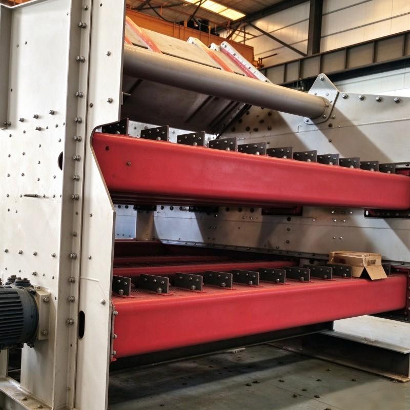
Stroke is the peak-to-peak displacement of the screen deck during vibration. It determines the energy imparted to the material bed.
What Is Frequency (Speed)?
Frequency is the number of vibration cycles per unit time, typically expressed in RPM or Hz. It determines how often particles contact the screen surface.
What Is Bed Depth?
Bed depth is the thickness of the material layer on the screen deck. At the discharge end, it should be 4–6 times the media opening size.
Working Principle
How Stroke and Frequency Affect Screening
-
Stroke provides energy to break up lumps and stratify material.
-
Frequency determines particle-surface contact frequency.
-
Fine screening: less stroke (thinner bed), higher frequency (more contacts).
-
Coarse screening: more stroke (breaks lumps), lower frequency (less bouncing).
-
Bed depth: controlled by stroke, speed, and feed rate.
Benefits
Benefits of Optimized Stroke and Frequency
-
Better stratification — fines reach the surface
-
Improved screening efficiency — sharper separation
-
Reduced blinding/pegging — addressed through settings
-
Extended bearing life — avoid excessive speed
-
Lower operating costs — efficient screening
-
Stable product quality — consistent cut size
Applications
Screening Applications Where Stroke and Frequency Matter
-
Iron ore screening — high tonnage, abrasive
-
Coal screening — wet, sticky material
-
Aggregates screening — sharp, heavy material
-
Gold ore screening — abrasive quartz
-
Copper ore screening — high capacity
-
Fertilizer screening — chemical resistance
Material Comparison
Fine vs Coarse Screening Settings
| Parameter | Fine Screening | Coarse Screening |
|---|---|---|
| Stroke | Less (lower amplitude) | More (higher amplitude) |
| Speed | Higher (800–1,000+ RPM) | Lower (800–1,000 RPM) |
| Bed Depth | Shallow | Deeper |
| Media | Fine polyurethane | Rubber, heavy wire |
Application Comparison
Setting Adjustments by Symptom
| Symptom | Primary Adjustment | Secondary Adjustment |
|---|---|---|
| Poor stratification | Increase stroke | Increase speed |
| Blinding | Increase speed | Increase stroke |
| Plugging/pegging | Increase stroke | Check media |
| Material bouncing | Reduce speed | Increase stroke |
| Bearing failure | Reduce speed | Check alignment |
Industry Application Matrix
| Industry | Typical Setting Challenge | Primary Solution |
|---|---|---|
| Iron Ore | High tonnage; thick bed | Increase stroke; control feed |
| Coal | Wet, sticky; blinding | Increase speed; anti-blinding media |
| Aggregates | Sharp, heavy; plugging | Increase stroke; check media |
| Gold Ore | Abrasive; bearing life | Reduce speed; regular maintenance |
| Copper Ore | High capacity | Optimize bed depth |
| Fertilizer | Chemical resistance | Polyurethane panels |
Selection Guide
Step-by-Step Stroke and Frequency Optimization
Step 1: Measure Current Settings
-
Use stroke card or vibration analyzer
-
Measure stroke (mm) and speed (RPM)
-
Check for “off-motion”
Step 2: Establish Baseline
-
Compare to typical ranges: stroke 8–12 mm; speed 800–1,000 RPM
-
Document current bed depth
Step 3: Match to Duty
-
Fine screening: reduce stroke, increase speed
-
Coarse screening: increase stroke, reduce speed
Step 4: Address Symptoms
-
Blinding: increase speed first
-
Plugging/pegging: increase stroke
Step 5: Target Bed Depth
-
Measure at discharge end
-
Target 4–6× media opening size
Step 6: Protect Bearing Life
-
Don’t run faster than necessary
-
Speed kills bearing life exponentially
Step 7: Work with Manufacturer
-
Use VSMA formula for optimum capacity
-
Provide actual feed data
Procurement Guide
Key Considerations When Procuring Screen Media for Optimized Settings
Required Information:
-
Screen model and size
-
Panel dimensions and aperture size
-
Material type and size
-
Current stroke and speed settings
-
Operating conditions
Supplier Evaluation Checklist:
-
□ Does the supplier offer media compatible with your settings?
-
□ Can they provide technical support?
-
□ Do they offer anti-blinding designs?
-
□ What is the typical lead time?
-
□ Can they provide references?
Buyer Questions to Ask:
-
“What media do you recommend for my stroke and speed?”
-
“Can you provide anti-blinding panels?”
-
“What is the expected panel life?”
-
“Do you offer trial programs?”
Failure Analysis
| Problem | Possible Cause | Recommended Solution |
|---|---|---|
| Poor stratification | Incorrect stroke/speed | Adjust to match duty |
| Blinding | Speed too low | Increase speed |
| Plugging/pegging | Stroke too low | Increase stroke |
| Material bouncing | Speed too high | Reduce speed |
| Bearing failure | Excessive speed | Reduce speed; check alignment |
| Off-motion | Worn springs, loose fasteners | Inspect and replace |
| Short panel life | Incorrect settings | Optimize stroke and speed |
Maintenance Guide
Recommended Maintenance Schedule
| Frequency | Task |
|---|---|
| Daily | Visual inspection; check for blinding |
| Weekly | Check stroke and speed; look for off-motion |
| Monthly | Inspect springs and fasteners |
| Quarterly | Full vibration audit; document settings |
| Annually | Replace worn components; recalibrate |
Preventive Maintenance Tips
-
Measure stroke and speed quarterly — settings drift
-
Check for off-motion — worn springs, loose fasteners
-
Monitor bearing temperature — speed kills bearings
-
Target bed depth — 4–6× media opening
-
Record settings — establish baseline
Case Study
Case Study: Optimizing Stroke and Frequency at a Coal Preparation Plant
Customer Type: Coal preparation plant
Ore Type: Coal, high moisture
Operating Conditions: 200 tph feed, 6 mm aperture
Problem:
The plant was experiencing severe blinding and poor screening efficiency. The screen was running at 1,100 RPM with 6 mm stroke. Bed depth was excessive, and bearing failures were frequent.
Solution:
The plant implemented:
-
Speed reduced from 1,100 to 900 RPM
-
Stroke increased from 6 to 10 mm
-
Bed depth controlled to 4× media opening
-
Blinding addressed by increasing speed temporarily
Result:
-
Screening efficiency improved from 65% to 88%
-
Bearing life extended by 2× (from speed reduction)
-
Blinding reduced by 70%
-
Annual savings: $680,000
-
Investment payback period: less than 2 months
FAQ
Question 1: What is the general rule for stroke and speed?
Answer: Finer screening requires less stroke and higher speed; coarse separation needs increased stroke and lower speed. This creates the right bed depth and particle-surface contact for each duty.
Question 2: What are typical target ranges for stroke and speed?
Answer: Stroke: 8–12 mm. Speed: 800–1,000 RPM. These are starting points for most aggregate and mining applications; optimal values depend on material characteristics.
Question 3: How does speed affect bearing life?
Answer: Speed kills bearing life exponentially. Reducing speed by 10% can double bearing life; increasing it by 10% can cut it in half. Only run as fast as necessary.
Question 4: What is the target bed depth?
Answer: 4 to 6 times the media opening size at the discharge end. For example, a ¼-inch media opening should have a bed depth of roughly 1.25 inches.
Question 5: How do I address blinding vs pegging?
Answer: Blinding → increase speed first (breaks surface tension). Plugging/pegging → increase stroke (kicks out near-size material).
Question 6: How do I verify actual motion?
Answer: Use a stroke card or vibration analyzer to measure actual stroke and RPM. Check for “off-motion”—distorted or varying motion caused by worn springs, loose fasteners, or material buildup.
Question 7: What is the VSMA formula?
Answer: The VSMA formula is used by most manufacturers to determine optimum capacity. The specific combination of speed and stroke that works for your material is best established with application engineers using actual feed data.
Question 8: What is the quick checklist for optimization?
Answer: (1) Measure first—audit stroke, speed, deck angle. (2) Match to duty—fine: less stroke, higher speed. (3) Target bed depth: 4–6× media opening. (4) Address symptoms—blinding → speed; plugging → stroke. (5) Protect machine—don’t run faster than necessary.
Conclusion
Optimizing vibrating screen stroke and frequency is fundamentally about matching the machine’s motion to your material’s specific characteristics.
Key Takeaways:
-
Fine screening — less stroke, higher speed
-
Coarse separation — more stroke, lower speed
-
Typical ranges — stroke 8–12 mm; speed 800–1,000 RPM
-
Bed depth — 4–6× media opening at discharge
-
Blinding — increase speed first
-
Plugging/pegging — increase stroke
-
Speed kills bearing life exponentially — 10% increase can cut life in half
-
Verify actual motion — use stroke card or vibration analyzer
Match motion to material. Measure first. Target bed depth of 4–6× media opening. Protect bearing life—speed kills exponentially. Work with your manufacturer using actual feed data.
Related Articles
Related Products:
Related Technical Guides:
Related Comparison Guides:
Related Process Hubs:
Contact Us
We warmly welcome customers from around the world to contact us and establish mutually beneficial partnerships.
Contact: Annie Lu
Email: annie.lu@huataogroup.com
Phone / WhatsApp: +86 180 3242 2676
Website: https://www.tufflexscreen.com/
Tags: Vibrating Screen, Stroke, Frequency, Screening, Bed Depth, Mineral Processing, Screening Equipment, Tufflex Screen, Off-Motion, VSMA Formula
Tags:
 admin
personal profile