How Often Should I Replace Hydrocyclone Liners?
Oct 20, 2026
 admin
admin
What factors affect hydrocyclone selection in mineral processing?
Hydrocyclone selection depends on ore characteristics (hardness, density, clay content, particle size distribution), liner material (polyurethane, rubber, ceramic), operational parameters (feed pressure, apex size, pulp density), and plant layout constraints. Field experience adds water split behavior, pressure stability range, and liner failure mode analysis—factors often missing from theoretical selection charts.
✔ Ore rheology affects separation more than lab tests predict—clay and liberation morphology matter
✔ Water split to underflow controls grinding circuit density—ignore this and mill performance suffers
✔ Apex size and feed pressure have the largest combined effect on cut point (d50)
✔ A cyclone stable at ±20% pressure fluctuation is worth more than one with perfect single-point efficiency
✔ Liner material must match wear mechanism (impact vs abrasion vs corrosion), not just abrasion index
✔ Plant layout (feed pipe geometry, height, crane access) often overrides theoretical sizing
| Item | Description |
|---|---|
| Function | Solid-liquid classification using centrifugal force |
| Key components | Inlet head, vortex finder, cone section, apex (spigot) |
| Liner materials | Polyurethane screen panel grades, natural rubber, alumina ceramic, silicon carbide |
| Cut point range | 20–400 µm (depending on diameter and pressure) |
| Applications | Grinding circuits, desliming, tailings, dense media, sand washing |
| Service life | 3–24 months depending on ore abrasiveness and liner selection |
| Maintenance frequency | Daily visual inspection; monthly internal inspection |
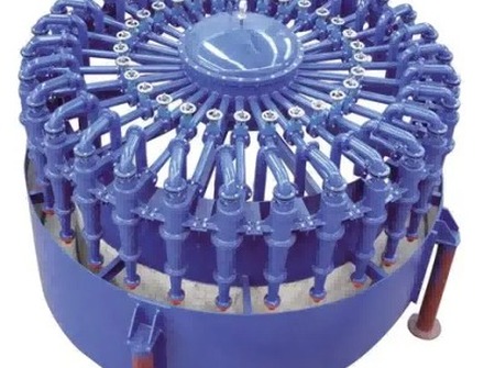
A hydrocyclone is a static classification device that uses centrifugal force generated by tangential feed injection to separate solid particles by size, density, and shape. It is the most common classifier in modern mineral processing grinding circuits, replacing spiral classifiers in most fine applications due to its smaller footprint, higher capacity, and lower water consumption.
For mines processing gold, copper, iron ore, lithium, or silica sand, hydrocyclone performance directly affects:
The working principle follows five physical stages:
Stage 1 – Tangential acceleration: Slurry enters the cylindrical inlet head through a tangential or involute feed box at 40–150 kPa pressure. This creates a high-velocity spinning vortex.
Stage 2 – Centrifugal classification: Centrifugal forces (typically 20–200× gravity) throw dense and coarse particles outward toward the cyclone wall. Fine and light particles remain near the central axis.
Stage 3 – Air core formation: A low-pressure air core forms along the axis. This air core is essential for stable classification—without it, separation collapses.
Stage 4 – Underflow discharge: Coarse particles spiral down the cone section and exit through the apex (spigot). Underflow typically contains 70–80% solids by weight in grinding applications.
Stage 5 – Overflow discharge: Fine particles and water exit through the vortex finder at the top. Overflow solids concentration typically ranges from 20–40% by weight.
| Benefit | Engineering explanation |
|---|---|
| High specific capacity | 10–500 t/h per cyclone depending on diameter |
| Small footprint | 1–2 m² per cyclone vs 20–50 m² for spiral classifier |
| No moving parts | Mean time between failures (MTBF) > 10,000 hours typical |
| Wide adjustable range | Change apex or vortex finder to shift cut point |
| Low water consumption | No wash water required unlike spiral classifiers |
| Easy to cluster | 2–20 cyclones in parallel for high tonnage circuits |
| Low initial cost | 30–50% lower capital cost than equivalent spiral classifier |
Hydrocyclones are used across the following industries and processes:
Mining and mineral processing:
Aggregates and industrial minerals:
Tailings management:
Coal preparation:
| Parameter | Hydrocyclone | Spiral Classifier |
|---|---|---|
| Cut point range | 20–400 µm | 100–1,000 µm |
| Floor space (per 100 t/h) | 5–10 m² | 50–100 m² |
| Water consumption | None (self-contained) | 0.5–1.5 m³/t feed |
| Maintenance cost (annual) | Low (liner replacement) | Medium (gear, shoes, bearings) |
| Installation height | 2–4 m | 3–5 m |
| Best application | P80 < 150 µm, fine grinding | P80 > 300 µm, washing circuits |
| Parameter | Polyurethane Screen Panel (vibrating screen) | Hydrocyclone |
|---|---|---|
| Cut point range | 0.5–50 mm | 20–400 µm |
| Efficiency (sharpness) | Very high (near ideal) | Medium (bypass inevitable) |
| Energy consumption | Low (screen vibration) | Medium (slurry pump) |
| Maintenance | Screen panel replacement | Liner replacement |
| Best application | Dry or wet sizing > 0.5 mm | Wet classification < 400 µm |
Verdict: For fine classification (< 400 µm) in wet grinding circuits, hydrocyclones are standard. Screens are superior for sharp separation but cannot achieve sub-100 µm cut points economically.
| Material | Abrasion resistance | Impact resistance | Corrosion resistance | Cost | Typical wear life (relative) | Best application |
|---|---|---|---|---|---|---|
| Natural rubber (60–70 Shore A) | Medium | Excellent | Good (except oil) | Low | 1× | Medium abrasion, sharp/angular particles |
| Polyurethane elastomer | Medium-high | Good | Good | Medium | 1.5–2× | Medium abrasion, fine classification |
| Alumina ceramic (92–99%) | High | Poor | Excellent | Medium-high | 4–6× | High abrasion, low impact |
| Silicon carbide ceramic | Very high | Poor | Excellent | High | 8–12× | Extreme abrasion (iron ore, copper) |
| Cast basalt | Medium | Poor | Good | Low-medium | 2–3× | Abrasion, low impact, low cost |
Selection rule: Match material to the dominant wear mechanism:
| Application | Recommended diameter | Recommended liner | Typical apex size | Typical cut point (d50) |
|---|---|---|---|---|
| Primary ball mill classification (copper) | 500–660 mm (20–26″) | Silicon carbide | 100–150 mm | 120–180 µm |
| Secondary ball mill classification (gold) | 250–350 mm (10–14″) | Rubber or polyurethane | 50–75 mm | 75–106 µm |
| Regrind mill classification | 150–250 mm (6–10″) | Polyurethane | 25–40 mm | 40–75 µm |
| Tailings dewatering (coarse) | 350–500 mm (14–20″) | Rubber | 80–120 mm | 75–150 µm |
| Silica sand washing | 150–250 mm (6–10″) | Rubber or polyurethane | 30–50 mm | 40–75 µm |
| Dense medium cyclone (coal) | 500–800 mm (20–32″) | Ceramic | Variable | 0.5–2 mm (d50c) |
| Desliming ahead of flotation | 250–350 mm (10–14″) | Polyurethane | 40–60 mm | 20–45 µm |
| Industry | Ore type | Common cut point | Typical challenges | Recommended liner |
|---|---|---|---|---|
| Gold | Free-milling, sulfide | 75–106 µm | Over-grinding, clay | Rubber or polyurethane |
| Copper | Porphyry | 120–180 µm | Abrasion, particle misplacement | Silicon carbide |
| Iron ore | Hematite/magnetite | 150–250 µm | Extreme abrasion, high density | Silicon carbide |
| Lithium | Spodumene, clay-rich | 100–150 µm | Clay rheology, blockage | Polyurethane |
| Lead-zinc | Massive sulfide | 100–150 µm | Medium abrasion, corrosion | Rubber |
| Silica sand | Quartz | 40–75 µm | Fine bypass, sharp particles | Rubber or polyurethane |
| Tailings | Mixed | 20–45 µm | Blockage, variable feed | Polyurethane |
| Coal | Bituminous | 500–2,000 µm (DMC) | High media density | Ceramic |
Collect the following data before contacting any supplier:
| Parameter | Unit | Typical range | Why it matters |
|---|---|---|---|
| Ore specific gravity | – | 2.5–4.5 | Affects settling velocity |
| Feed solids (weight) | % | 30–65 | Affects viscosity and cut point |
| Target P80 | µm | 40–250 | Determines cyclone diameter |
| Feed P80 | µm | 500–5,000 | Affects required pressure |
| Throughput (dry) | t/h | 50–2,000 | Determines number of cyclones |
| Available pressure | kPa | 40–150 | Pump capability |
| Abrasion index (Ai) | – | 0.1–1.5 | Determines liner material |
As a first approximation:
Target cut point (d50) vs cyclone diameter:
| Desired d50 (µm) | Cyclone diameter (mm) | Typical applications |
|---|---|---|
| 20–40 | 100–150 | Fine regrind, desliming |
| 40–75 | 150–250 | Silica sand, regrind |
| 75–150 | 250–500 | Ball mill classification (gold, base metals) |
| 150–300 | 500–750 | Primary grinding (copper, iron ore) |
Number of cyclones = Total throughput ÷ (Single cyclone capacity)
Single cyclone capacity depends on diameter and pressure. Typical values:
| Diameter (mm) | Capacity at 50 kPa (t/h dry solids) |
|---|---|
| 150 | 15–30 |
| 250 | 40–80 |
| 350 | 80–150 |
| 500 | 150–300 |
| 660 | 250–500 |
Rule of thumb: Always include 1–2 standby cyclones in a cluster for maintenance without shutdown.
Initial apex selection: Apex diameter should be 30–50% of vortex finder diameter for normal classification.
Fine-tuning based on underflow pattern:
Follow the decision tree:
Question 1: Is feed highly abrasive (Ai > 0.6 or high quartz content)?
Question 2: Is coarse, angular tramp possible (impact risk)?
Question 3: Is corrosion present (low pH, chlorides)?
Process data:
Operating data:
Drawings and layout:
| Drawing type | Required for | Format accepted |
|---|---|---|
| Existing cyclone GA drawing | Retrofit | DWG, PDF, or sketch with dimensions |
| Plant layout (feed pipe routing) | New installation | CAD (DWG) or dimensioned PDF |
| Flange details (feed inlet) | Both | Drawing or standard specification |
| Underflow chute arrangement | Both | Dimensioned sketch |
If replacing an existing cyclone (Krebs, Weir, FLSmidth, Multotec, Cavex), provide:
HUATAO can manufacture direct replacements for most OEM cyclones with:
| Criteria | What to verify | Red flags |
|---|---|---|
| Factory ownership | Request factory audit or video tour | Trader with no manufacturing facility |
| Material wear data | Ask for wear life data for your ore type | Vague “good wear life” claims |
| CAD support | Ask for layout integration drawing | No engineering support available |
| Lead time | Confirm lead time in writing | Vague or >12 weeks |
| Stock availability | Ask about common apex/vortex finder stock | Must manufacture every single part from scratch |
| Quality system | ISO 9001 certification | No documented QA/QC |
| Reference list | Ask for 3 similar applications | No relevant references |
| Item | HUATAO standard |
|---|---|
| MOQ (complete cyclone) | 1 unit |
| MOQ (liners only) | Negotiable; typically 4 sets |
| Lead time (complete cyclone) | 4–6 weeks |
| Lead time (liners) | 2–4 weeks |
| Expedited lead time | Available at additional cost |
| Packaging | Plywood export cases with foam protection |
| Shipping | FOB Qingdao (standard) or CIF destination port |
| Inspection | Internal visual + hydrostatic pressure test (water) |
| Documentation | Packing list, commercial invoice, test certificate, material certificates |
HUATAO follows these inspection standards:
| Inspection item | Method | Acceptance criteria |
|---|---|---|
| Dimensional accuracy | CMM or calibrated gauges | ±1 mm on major dimensions |
| Liner hardness (rubber) | Shore A durometer | 60–70 Shore A |
| Liner hardness (polyurethane) | Shore A durometer | 85–95 Shore A |
| Ceramic liner integrity | Visual + tap test | No cracks, solid ring |
| Pressure test | Hydrostatic at 1.5× working pressure | No leakage for 30 minutes |
| Flange flatness | Straight edge + feeler gauge | <0.5 mm gap |
Visual indicator: Underflow discharges as a solid, rope-like stream instead of a spray cone.
Possible causes:
Solutions:
Visual indicator: Underflow discharges as a wide, thin spray with very coarse particles.
Possible causes:
Solutions:
Visual indicator: Overflow contains visible coarse sand particles.
Possible causes:
Solutions:
Visual indicator: Pressure gauge needle swings >10 kPa.
Possible causes:
Solutions:
Visual indicator: Liners wear through before expected service life.
Possible causes:
Solutions:
| Failure mode | Primary cause | Secondary cause | Immediate action | Long-term solution |
|---|---|---|---|---|
| Roping | Apex too small | Low pressure | Increase apex size | Size correctly from start |
| Spraying | Apex too large | Worn vortex finder | Reduce apex size | Regular wear monitoring |
| Coarse overflow | Worn vortex finder | High feed density | Replace vortex finder | Density control system |
| Pressure fluctuation | Pump surging | Partial blockage | Stabilize pump | Install pressure transmitter |
| Premature wear | Wrong material | High pressure | Upgrade liner material | Application-specific selection |
Time required: 5–10 minutes per cyclone cluster
| Task | Method | Action if abnormal |
|---|---|---|
| Observe underflow pattern | Visual | Rope → increase apex; Spray → decrease apex |
| Check feed pressure | Read pressure gauge | Fluctuation → check pump; Low → increase speed |
| Listen for noise | Auditory | Whistling/rattling → schedule inspection |
| Check for leakage | Visual at flanges | Leak → tighten bolts or replace gasket |
Time required: 30–60 minutes per cluster
| Task | Method | Acceptance criteria |
|---|---|---|
| Inspect apex for oval wear | Go/no-go gauge or visual | Replace if >10% oval or >70% wall reduction |
| Check vortex finder diameter | Internal caliper measurement | Replace if >5% over original diameter |
| Inspect feed pipe erosion | Visual and thickness check | Schedule replacement if <50% thickness |
| Check flange bolt torque | Torque wrench | Torque to specification (typically 200–400 N·m) |
Time required: 2–4 hours per cyclone (isolated)
Step-by-step procedure:
| Application | Apex life | Vortex finder life | Cone liner life | Upper head life |
|---|---|---|---|---|
| Gold (rubber liners) | 3–4 months | 6–8 months | 6–9 months | 12–18 months |
| Copper (ceramic liners) | 8–12 months | 12–18 months | 12–18 months | 18–24 months |
| Iron ore (ceramic liners) | 6–9 months | 9–12 months | 9–12 months | 12–18 months |
| Lithium (polyurethane) | 4–6 months | 6–9 months | 6–9 months | 9–12 months |
| Silica sand (rubber) | 2–4 months | 4–6 months | 4–6 months | 6–9 months |
Note: These are guidelines. Actual life depends on ore abrasiveness, operating pressure, and maintenance quality. Keep historical records to refine your specific schedule.
For a cluster of 4 cyclones, recommend stocking:
| Part | Quantity | Reason |
|---|---|---|
| Apex (most common size) | 6 | Highest wear rate |
| Apex (next size up and down) | 2 each | For fine-tuning |
| Vortex finder (most common size) | 4 | Second highest wear |
| Complete liner set (one cyclone) | 2 | For unplanned failures |
| Gasket set | 10 | Low cost, high downtime risk |
| Flange bolts (M24–M30, various lengths) | 20 | Corrosion risk |
Customer Type: Gold concentrator, West Africa
Operating conditions: 350 t/h SAG mill circuit, target P80 106 µm. Existing hydrocyclone cluster (6 × 350 mm) from competitor brand.
Problem:
Root cause analysis:
HUATAO engineers conducted on-site audit:
Solution provided:
Results (measured after 3 months):
| Metric | Before | After | Improvement |
|---|---|---|---|
| Recirculating load | 350–400% | 240–270% | -30% |
| Cyclone availability | 91% | 97% | +6% |
| Liner life (lower cones) | 4 months | 14 months | 3.5× |
| Roping frequency | 8× per day | <1× per week | -95% |
| Grinding energy per ton | 18.2 kWh/t | 16.1 kWh/t | -11.5% |
Customer quote:
“The HUATAO team didn’t just sell us liners—they diagnosed our circuit and corrected our apex sizing. The ceramic cones paid for themselves in three months.”
Question 1: How much does a mining hydrocyclone cost?
Answer: Price depends on diameter, liner material, and whether it’s a single unit or cluster. Typical ranges:
Question 2: How do I choose between polyurethane, rubber, and ceramic liners?
Answer: Use this decision rule:
Question 3: Can I use HUATAO hydrocyclones as direct replacements for Krebs, Weir, or FLSmidth cyclones?
Answer: Yes. HUATAO manufactures drop-in replacements for most major OEM cyclones. Provide your existing model number or a GA drawing with flange dimensions, and we will match the external geometry exactly. Internal liners can be upgraded to better materials at the same time.
Question 4: How often should I replace hydrocyclone liners?
Answer: Replacement frequency depends on ore abrasiveness and operating pressure:
Question 5: What causes roping and how do I fix it immediately?
Answer: Roping (solid plug discharge) is caused by apex too small or feed pressure too low. Immediate fix: Increase apex diameter to next available size. If no larger apex available, increase feed pressure by 10–15% (check pump speed). Long-term: Recalculate apex sizing based on actual solids loading.
Question 6: Do you supply custom hydrocyclones for non-standard applications?
Answer: Yes. HUATAO designs and manufactures custom cyclones for specialized applications including:
Question 7: What is your MOQ and lead time?
Answer:
Question 8: How do I verify a hydrocyclone supplier’s manufacturing capability?
Answer: Request the following before ordering:
Question 9: Can I reduce hydrocyclone maintenance costs?
Answer: Yes, through three strategies:
Question 10: What information do you need to quote a hydrocyclone?
Answer: Provide:
Hydrocyclone selection is a multi-factor engineering decision that cannot be reduced to a single chart or software output. The best selection process combines:
When these four layers align, the hydrocyclone delivers:
When any layer is ignored, the result is roping, coarse overflow, premature wear, or circuit instability.
At HUATAO, we apply this four-layer approach to every hydrocyclone we supply. We don’t just sell equipment—we provide application engineering, material matching, and ongoing support.
Contact:
Annie Lu
Email: annie.lu@huataogroup.com
Phone / WhatsApp: +86 180 3242 2676
Website: http://www.tufflexscreen.com
We warmly welcome customers from around the world to contact us and establish mutually beneficial partnerships.
Hydrocyclone Selection, Mineral Processing Cyclone, Grinding Circuit Classification, Polyurethane Screen, Mining Wear Parts, Cyclone Liner, Ceramic Liner, Rubber Liner, Copper Mining Cyclone, Gold Processing, Iron Ore Classification, Lithium Beneficiation, Tailings Dewatering, Silica Sand Washing, Krebs Cyclone Replacement, Weir Cyclone Replacement, FLSmidth Cyclone Replacement, Multotec Cyclone Alternative
admin