
The optimal number of hydrocyclones in a cluster is found by dividing the total feed flow rate by the capacity of a single cyclone at your target pressure. However, a practical design should always include 20-30% more positions than this minimum to allow for maintenance and redundancy. The final number is also heavily influenced by the desired cut point (d50) and the choice between a few large or many small cyclones.
✔ The core formula is N = Q_total / Q_cyclone, where Q_cyclone is dependent on pressure and d50.
✔ Smaller cyclones produce finer cuts but increase maintenance complexity.
✔ Larger cyclones are more robust but limited to coarser separations.
✔ Uneven feed distribution is a primary cause of poor cluster performance.
✔ New installations require daily density checks of individual cyclones to validate design.
| Item | Description |
|---|---|
| Function | Particle classification based on size and density for the grinding circuit. |
| Core Calculation | N = Total Feed Flow (m³/h) / Single Cyclone Capacity (m³/h) |
| Key Variable | Single cyclone capacity is affected by operating pressure and cut point (d50). |
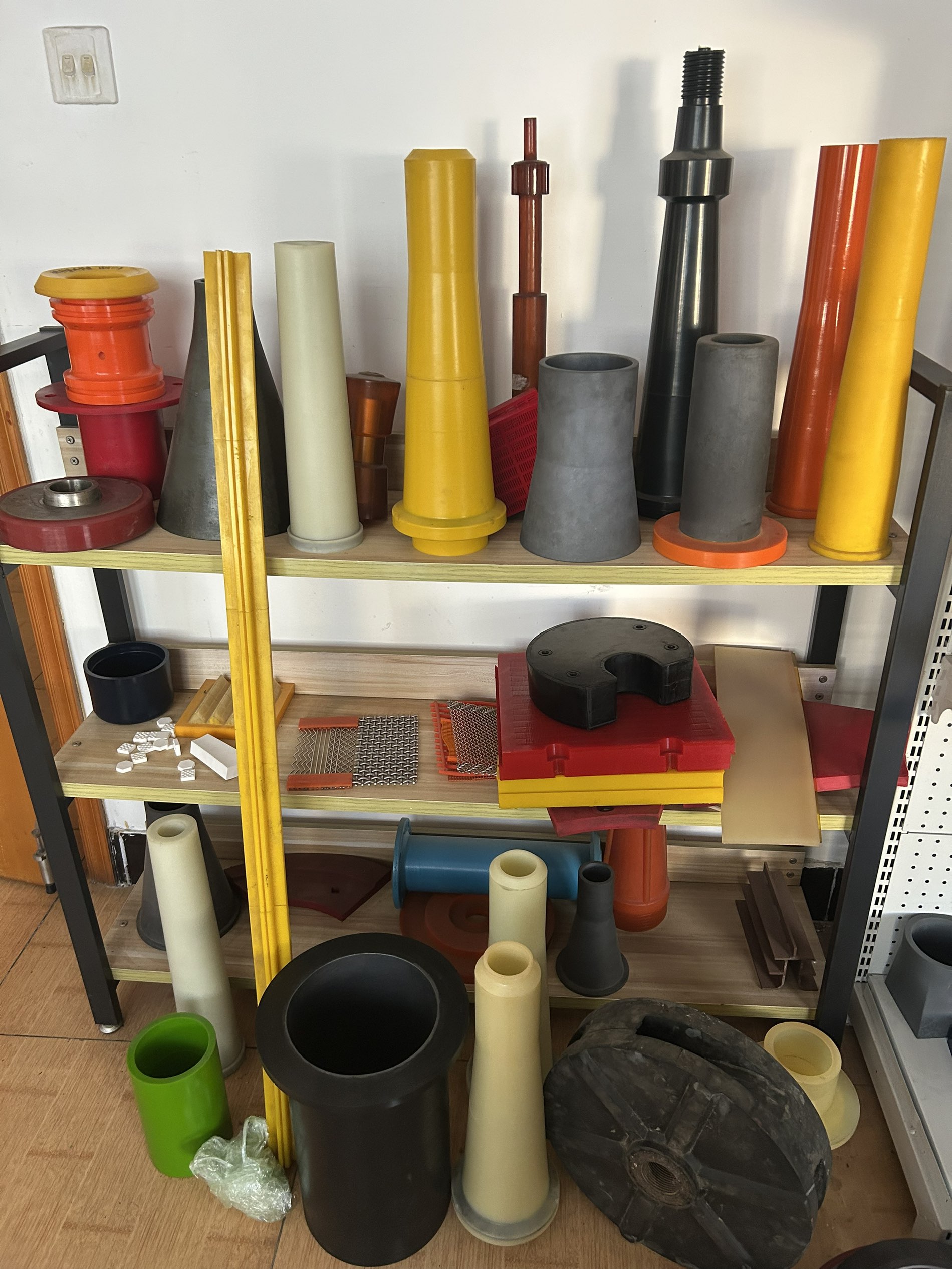
| Material | Body is often steel or rubber-lined; high-wear areas use polyurethane (PU) or ceramic liners. |
| Service Life | Highly dependent on ore abrasiveness and liner material; PU liners offer the best balance of life and cost. |
The hydrocyclone cluster is a critical component in any mineral processing plant, responsible for the crucial task of classification. Its performance directly impacts the efficiency of downstream processes like flotation and dewatering. For engineers, the question, "How many hydrocyclones do I need?" is a common but complex design challenge. This guide breaks down the process, covering the calculations, material choices, and practical considerations to help you design a cluster that delivers optimal performance and a strong return on investment.
What is a Hydrocyclone Cluster?
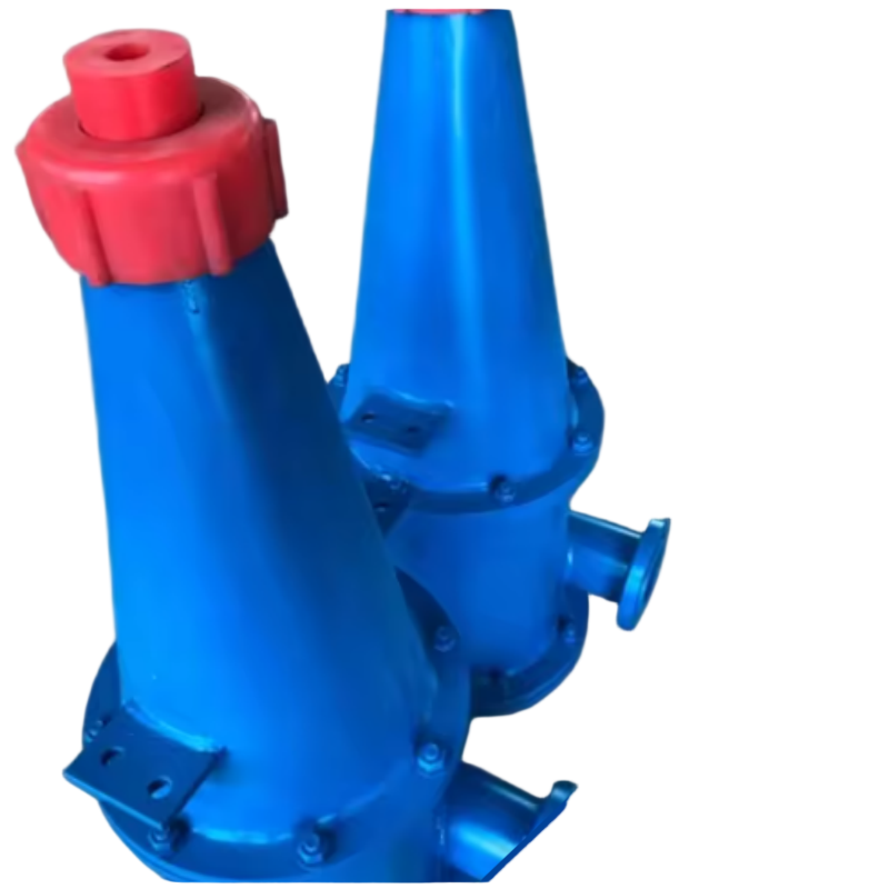
A hydrocyclone cluster is an assembly of multiple hydrocyclones operating in parallel. They are used to handle large volumes of slurry in a mineral processing plant. Each cyclone in the cluster uses centrifugal force to separate particles based on size and density. The slurry is fed tangentially into the top, creating a powerful vortex. This action forces heavier, coarser particles to the walls and down to the underflow (apex), while finer, lighter particles move to the center and exit through the overflow (vortex finder). This classification is crucial for closing the grinding circuit and ensuring the correct particle size for subsequent stages like flotation.
A cluster's capacity is simply the sum of its individual units, allowing for modular scaling to match varying plant throughput. For example, if a single High Wear Resistance PU Lined Hydrocyclone For Mining has a capacity of 200 m³/h, a cluster of six would have a total capacity of 1,200 m³/h.
The journey to the optimal number of cyclones begins with your process data.
Define Your Parameters:
Total Feed Flow Rate (Q_total): The volume of slurry the cluster must process.
Operating Pressure: This is not a fixed variable. It is a key design parameter that affects both capacity and cut size.
Desired Cut Point (d50): The particle size at which there is a 50% chance of reporting to the underflow or overflow. This is dictated by your downstream process.
Calculate Single Cyclone Capacity (Q_cyclone):
Each cyclone diameter has a specific capacity at a given pressure and density. This data is usually obtained from the manufacturer. For example, a 500mm cyclone might handle 150-200 m³/h at 60 kPa.
Determine the Minimum Number of Cyclones (N):
N = Q_total / Q_cyclone
Example:
Total Feed Flow: 1,800 m³/h
Single Cyclone Capacity: 200 m³/h
Minimum Cyclones: 1,800 / 200 = 9 cyclones.
Once you have a theoretical count, you must decide on the cyclone diameter. This is one of the most impactful decisions you will make.
Multiple Smaller Cyclones:
Advantage: They generate a higher centrifugal force, allowing for a finer separation. They also offer more flexibility to turn units on and off to match throughput changes.
Disadvantage: They have a smaller apex. This makes them more susceptible to blockages and requires more frequent maintenance. More cyclones also mean more wear parts to manage, increasing inventory costs.
Fewer Larger Cyclones:
Advantage: They are more robust and handle higher throughput. Larger apexes are less prone to clogging, reducing maintenance and downtime. They have a simpler configuration and fewer parts.
Disadvantage: They cannot achieve the same fine cuts as smaller cyclones.
Real-World Advice: In many cases, the operational simplicity and lower maintenance cost of a larger cyclone make it the better choice, provided the required cut point can still be achieved. The total cost of ownership often favors a more robust, simpler system.
Configuring cyclones in parallel allows for operational flexibility and redundancy.
Operational Flexibility: In a parallel configuration, individual units can be switched online or offline to maintain efficient classification as feed conditions change. For instance, if the feed rate drops, you can shut down a few cyclones to maintain optimal pressure and cut point in the remaining units.
Redundancy: This is where the wisdom of "designing for reality" comes in. Wear is inevitable. When a cyclone wears out or blocks, you need to take it offline for maintenance. If you only installed the theoretical minimum of 9 units, taking one offline would reduce capacity to 1,600 m³/h, potentially bottlenecking the circuit.
A Key Operational Dynamic: Operating pressure is not fixed; it changes dynamically as you turn cyclones on and off. For example, if you design a system for 6 cyclones but operate with only 4, the flow per unit increases, raising the pressure and potentially shifting your d50 finer. Your process control strategy must account for this.
You can have the perfectly calculated number of cyclones, but if your distributor is poor, the entire cluster will underperform. Uneven feed distribution is the most common cause of poor cluster performance.
The Problem: A poorly designed manifold will feed more slurry to the cyclones in the middle of the cluster and starve the ones at the ends. This causes some cyclones to cut coarser while others cut finer, resulting in a poor overall separation curve.
The Solution: The field-proven solution is to use a radial or symmetrical feed distributor. These are designed to split the flow evenly, ensuring that the pressure drop across each cyclone's inlet is within 5% of the target. Proper distribution is more important than the number of cyclones themselves.
Your calculations provide a baseline, but the real world has a habit of introducing variables.
Pilot Testing: The most reliable way to predict performance is with a pilot test using full-scale cyclones. If this is not feasible, scaling from smaller diameters is possible but limited to a ratio of 1:3 for accuracy.
On-Site Validation: When commissioning a new cluster, the first two weeks are the most critical. Conduct daily measurements of the underflow and overflow densities from each individual cyclone. This is a straightforward but powerful check. If one cyclone has a significantly different underflow density, it’s a clear sign of uneven flow distribution or abnormal wear. This allows you to make immediate adjustments to the distributor or schedule maintenance, preventing long-term efficiency losses.
The performance of a hydrocyclone doesn't just depend on its design; it also relies on the quality of its wear parts. The feed inlet, cylindrical and conical sections, apex, and vortex finder are all subject to constant abrasion. Choosing the right material is key to minimizing downtime and total cost of ownership.
Polyurethane (PU): This is the ideal material for most hydrocyclone wear parts. It provides an excellent balance of abrasion resistance, flexibility (it doesn't crack like ceramic), light weight (easy to handle), and corrosion resistance. PU liners generally offer the lowest total cost per ton.
Ceramic: Offers the highest level of abrasion resistance. It is recommended for the most extreme applications where PU doesn't provide sufficient life. However, it is brittle, more expensive, and requires careful handling to avoid cracking.
Rubber: A lower-cost option that provides good abrasion resistance. However, it is less durable than PU in high-velocity applications.
Product Recommendation: At HUATAO GROUP, we specialize in manufacturing high-quality polyurethane wear parts. Our High Wear Resistance PU Lined Hydrocyclone For Mining is a prime example of how advanced material technology can extend the service life of your cluster and reduce your operating costs.
Customer Type: Copper-Molybdenum Mine, Mexico
Ore Type: Copper-Molybdenum Porphyry
Operating Conditions: High circulating load, variable feed density.
Problem: The mine operated a cluster of three hydrocyclones. The performance was erratic, with high circulating load variability. The cluster was inefficient, and the operators struggled to maintain a stable cut point.
Solution: The plant performed a detailed audit. The key finding was that the system was over-cycloned. By reducing the active cyclones from three to two and balancing the feed pressure, the hydraulic balance within the cluster was dramatically improved.
Result:
Improved Balance: Slurry split was reduced from 1.818 to 1.116, indicating a far more stable and predictable separation.
Increased Stability: The circulating load variability was lowered significantly, leading to more stable grinding and flotation operations.
Cost Savings: The optimized cluster achieved the same throughput with one less active cyclone, reducing wear part consumption and the associated maintenance costs.
Start with Mass Balance: Before selecting any equipment, complete a formal mass balance calculation to establish the required d50, throughput, and solids recovery for your specific ore.
Calculate Theoretical Minimum: Use the formula N = Q_total / Q_cyclone to determine the baseline number of cyclones.
Select Diameter: Choose the largest cyclone diameter that can still achieve your required d50. Always consider the trade-off between separation efficiency and maintenance complexity.
Plan for Reality: Add 20-30% to your theoretical number for redundancy. This allows you to perform maintenance without shutting down the entire grinding circuit.
Design the Distributor: Engage with an engineering firm to design a proper radial or symmetrical distributor that ensures equal flow to each cyclone.
Specify Quality Wear Parts: Invest in high-quality wear parts, like those from HUATAO GROUP, to maintain your designed performance and reduce your total cost of ownership.
When sourcing your hydrocyclone cluster or replacement parts, use this checklist:
Required Information for Supplier:
Ore type and abrasiveness
Slurry feed rate (m³/h)
Feed pulp density (% solids)
Desired d50 cut point
Operating pressure range
Drawings and Specifications:
Provide detailed engineering drawings if it's a custom installation.
If it's an OEM replacement, provide the OEM part numbers and dimensions.
Supplier Evaluation Checklist:
Can the supplier provide material reports and certifications?
Does the supplier have experience with similar ore types and applications?
Can the supplier provide wear-life recommendations?
Does the supplier have export experience to your country?
What is the supplier's MOQ and lead time for both the cluster and spare parts?
Daily: Visually inspect for leaks and check the feed pressure gauge. Listen for unusual noises or vibrations that could indicate a blockage.
Weekly: Check the apex and vortex finder for wear. A significant change in performance often points to wear in one of these critical components.
Monthly: Conduct a detailed inspection of the internal liners and measure the wear patterns. This will help you predict replacement intervals.
Spare Parts Inventory: Always keep critical spares on hand. A common stock is an extra set of apexes and vortex finders to minimize downtime during a change-out.
Q1: How do I calculate the required number of hydrocyclones?
A: You calculate the required number by dividing your total feed flow rate by the capacity of a single cyclone at the desired operating pressure.
Q2: What is the ideal operating pressure for a hydrocyclone?
A: There is no single "ideal" pressure. It depends on the desired cut point and capacity. Higher pressure increases capacity and shifts the cut point finer.
Q3: What is the difference between a hydrocyclone and a spiral classifier?
A: A hydrocyclone uses centrifugal force for a fast, high-capacity separation. A spiral classifier is an older technology that uses gravity and settling for a slower, coarser separation. Hydrocyclones generally offer higher efficiency and a smaller footprint.
Q4: How can I prevent uneven distribution in my cyclone cluster?
A: The solution is a well-designed, symmetrical or radial feed distributor. This ensures that each cyclone receives the same feed volume and pressure.
Q5: What are the most common wear parts in a hydrocyclone?
A: The high-wear areas are the feed inlet, the apex (spigot), and the vortex finder. The cylindrical and conical sections also require liners.
Q6: What is a vortex finder and what is its function?
A: The vortex finder is a component at the top of the cyclone that extends into the body. Its function is to control the overflow stream and establish the air core.
Q7: How can I extend the service life of my hydrocyclone wear parts?
A: Use the correct material for your ore type. For most applications, polyurethane offers a good balance of wear resistance and cost. Regular inspections and timely replacement are also crucial.
Q8: Why should I choose a polyurethane hydrocyclone liner?
A: Polyurethane offers an excellent balance of abrasion resistance, impact resistance, and cost-effectiveness. Unlike ceramic, it is flexible and won't crack. It typically provides the lowest total cost per ton.
Sizing a hydrocyclone cluster is a fundamental task for any mineral processing engineer. It requires a structured approach that balances theoretical calculations with practical operational needs. By following the steps outlined in this guide, including proper pressure and capacity calculations, selecting the right cyclone diameter, and most importantly, designing for redundancy and even feed distribution, you can build a cluster that significantly improves the efficiency of your grinding circuit and its downstream processes.
The longevity and consistent performance of this cluster depend on the quality of its components. High-quality polyurethane wear parts, such as the High Wear Resistance PU Lined Hydrocyclone For Mining, are essential for maintaining your designed separation efficiency and reducing your total operating costs.
Related Products
Related Technical Guides
Hydrocyclone Selection For Mineral Processing: Full Engineering Guide
What Size Hydrocyclone Do I Need For My Mineral Processing Plant?
How Do I Calculate Hydrocyclone Capacity For Mineral Processing
Related Buyer Guides
Related Comparison Articles
Annie Lu
Email: annie.lu@huataogroup.com
Phone / WhatsApp: +86 180 3242 2676
Website: http://www.tufflexscreen.com
can not be empty
can not be empty

HUATAO GROUP - SCREENS
ADD : No.298 Zhonghua North Street, Shijiazhuang 050000 China.
TEL : +86 0311 80690567
EMAIL :market@huataogroup.com
Web: www.tufflexscreen.com
 WhatsApp & WeChat : +86 18033763037